Patent-ly Obvious
Mind Control is "Patent"-ly Obvious
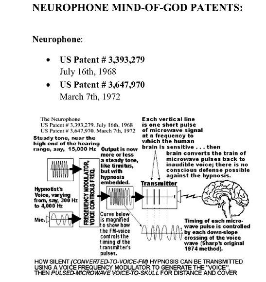
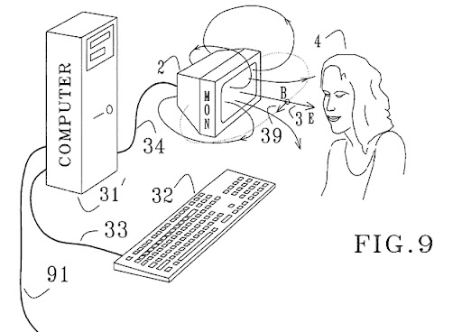
“Physiological
effects have been observed in a human subject in
response to stimulation of the skin with weak
electromagnetic fields that are pulsed with
certain frequencies near ½ Hz or 2.4 Hz, such as
to excite a sensory resonance. Many computer
monitors and TV tubes, when displaying pulsed
images, emit pulsed electromagnetic fields of
sufficient amplitudes to cause such excitation. It
is, therefore, possible to manipulate the nervous
system of a subject by pulsing images displayed on
a nearby computer monitor or TV set. For the
latter, the image pulsing may be embedded in the
program material, or it may be overlaid by
modulating a video stream, either as an RF signal
or as a video signal. The image displayed on a
computer monitor may be pulsed effectively by a
simple computer program. For certain monitors,
pulsed electromagnetic fields capable of exciting
sensory resonances in nearby subjects may be
generated even as the displayed images are pulsed
with subliminal intensity.”
https://cocatalog.loc.gov/cgi-bin/Pwebrecon.cgi?v1=1&ti=1,1&Search%5FArg=Vau001035955&Search%5FCode=DOCN&CNT=25&PID=nDXWednOBTvf-mPtbLc-_7Fk05X&SEQ=20210924125632&SID=1


- US
Patent Application 20070238252 - Cosmic
particle ignition of artificially ionized
plasma patterns in the atmosphere:
www.patentstorm.us/applications/20070238252/fulltext.html
DARPA_Restoring_Active_Memory_Dr_Matthew_Pava
Pose Estimation from Wi-Fi
---------------------------------------------------------------------------------------------------
US PATENT
5,507,291- METHOD AND ASSOCIATED APPARATUS FOR REMOTELY
DETERMINING A PERSON'S EMOTIONAL STATE --In a method for
remotely determining information relating to a person's
emotional state, an waveform energy having a predetermined
frequency and a predetermined intensity is generated and
wirelessly transmitted towards a remotely located subject.
Waveform energy emitted from the subject is detected and
automatically analyzed to derive information relating to the
individual's emotional state. Physiological or physical
parameters of blood pressure, pulse rate, pupil size,
respiration rate and perspiration level are measured and
compared with reference values to provide information
utilizable in evaluating interviewee's responses or possibly
criminal intent in security sensitive areas.

MODELING OF THE
ACOUSTO-........ELECTROMAGNETIC.... METHOD
FOR IONOSPHERE MONITORING
(Karpenko Physico-....Mechanical
Institute of the National
Academy
of Sciences of Ukraine):
http://www.ursi.org/Proceedings/ProcGA05/pdf/EP32%280275%29.pdf
Nervous system manipulation by electromagnetic fields from monitors):
https://patents.google.com/patent/US6506148B2/en
https://jrpomerantz.com/blog/the-7-patents-of-hendricus-g-loos/
Q. Who is Hendricus G. Loos?
A1.
Who is Hendricus G. Loos? That’s a good question. Real man or made up name used as a cover. Whoever he is, apparently he has been busy. Many different patents have been filed under this name. These include “nervous system manipulation by electromagnetic from monitors” and “subliminal acoustic manipulation of the nervous system”. These technologies have been around for a long time now and who can really say the full extent of how they’ve been used. You can see a list of all of them with the patent numbers here.
https://patents.justia.com/inventor/hendricus-g-loos
The name Hendricus G. Loos does not belong to a person, its a fictitious name. Perhaps the person working behind this name is Professor Ross Adey , who qualified in Medicine from Australia, then came to Oxford University to study brain physiology . Then he joined University of California in 1954, later joined the Brain Research Institute in 1961. He mainly studied the effects of ELF & microwaves on human brain and nervous system. He developed several devices for remote mind control and manipulation of nervous system which were later patented in US. There could be a few other such professionals and scientists, who developed the Mind Control devices under a single fictitious name ‘Dr Hendricus G. Loos’, actually working for DARPA or CIA, so as not to attract the attention of the Media or investigators.
As per available records Dr Hendricus G. Loos( fictitious ) was associated with Plasmadyne Corporation during the late fifties. He published an article about Yang-Mills field in 1969 in American Physical Society Journal. He had set up a shop in Fallbrook, California and developed Lagoona Research Laboratory. Then he worked with the department of Defence , US; department of Health & Human Services and Defence Advance Research Projects Agency ( DARPA) where he spent most of his time. In 2003 , he became the President of Cuewave Corporation. Dr Loos filed for business licence ( entity no-C2396570). Company’s own site www.cuewave.com is nothing more than a copy of site for advertising business. Any search for business yields nothing more than directory listings. The listings themselves provide little additional data other than the business is listed for commercial physical research and has a standard industrial classification (SIC) with code of 8731(10) This classifies them for commercial, physical and biological research. He is also referred to as Dr Henry Loos or Dr Hank Loos. Since 1978 , he has been awarded 11 patents by US for devices mainly aiming for human nervous system manipulation. Some examples are:
USP# 3009080- Apparatus and method for generating and containing plasma having ultra high temperatures.
USP# 4245909- An optical instrument for measurement of particle size distribution.
USP# 6238333- Remote magnetic manipulation of nervous systems.
USP# 6091994- Pulsative manipulation of nervous systems.
USP# 5782874- Method and apparatus for manipulating nervous system.
USP# 6017302- Subliminal acoustic manipulation of nervous system.
USP# 6506148-Nervous system manipulation by electromagnetic fields from monitor.
All devices are used for Mind Control projects run by CIA or other intelligence agencies. A group of researchers( under the name Dr H Loos) were actually a group of hired professionals for researching and inventing such devices which could be developed and used for mass mind control, PSYOPS, behaviour modification later by CIA.
A2.
its an anagram for Source Holdings
From Equations 2 and 1, I s =(I BB
/α)(1-R l )=i 1 +i 2
,
or (I BB /α)=(i 1 +i 2
)/(1-R l ). (15)
Combining Equations 14 and 15, the relationship of
Equation 16 is obtained. I e =i 1
/(1-R o )+(i 1 +i 2
)/(1-R l )(16)

Equation 6 gives blackbody radiation from
the earth's surface in terms of i 1
and i 2 and the three
reflectivities: I e =I BB
(T e )(1-R)+(I e
-i 1 )R I BB
(T e )=I e
+(R/(1-R))i 1
or I BB (T e )=i
1 /(1-R o )+(i 1
+i 2 )/(1-R l )+(R/(1-R))i
1 (17)
To
achieve a lower temperature of the earth,
(considering i 1 , i 2
and R as constants), it is
desirable to make R and R l
as small as possible.
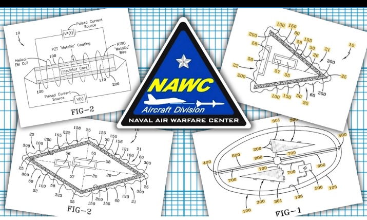
Navy’s
Advanced Aerospace Tech Boss Claims Key ‘UFO’ Patent Is Operable
Navy officials claim their radical electromagnetic and
superconductor technologies aren’t theoretical, they’re already
operable in some form.
Docs Show Navy Got ‘UFO’ Patent
Granted By Warning Of Similar Chinese Tech Advances
Patent documents indicate that the U.S. and China are actively
developing radical new craft that seem eerily similar to UFOs
reported by Navy pilots.
HAARP - Related Patents:
For those
who doubt the feasibility of these special
operations, just take a look at the following
Patents.
Chemtrail Patents:
Method and apparatus for altering a region in
the earth's atmosphere, ionosphere, and/or magnetosphere
United States
Patent 4,686,605 / Eastlund / August 11, 1987
A method and apparatus for
altering at least one selected region which normally exists
above the earth's surface. The region is excited by electron
cyclotron resonance heating to thereby increase its charged
particle density. In one embodiment, circularly polarized
electromagnetic radiation is transmitted upward in a
direction substantially parallel to and along a field line
which extends through the region of plasma to be altered.
The radiation is transmitted at a frequency which excites
electron cyclotron resonance to heat and accelerate the
charged particles. This increase in energy can cause
ionization of neutral particles which are then absorbed as
part of the region thereby increasing the charged particle
density of the region.
Method of
modifying weather
United
States Patent 6,315,213 / Cordani / November 13, 2001
A method for artificially modifying the
weather by seeding rain clouds of a storm with suitable
cross-linked aqueous polymer. The polymer is dispersed
into the cloud and the wind of the storm agitates the
mixture causing the polymer to absorb the rain. This
reaction forms a gelatinous substance which precipitate
to the surface below. Thus, diminishing the clouds
ability to rain.
Process for
absorbing ultraviolet radiation using dispersed
melanin
United
States Patent / 5,286,979 / Berliner / February 15, 1994
This invention is a process for
absorbing ultraviolet radiation in the atmosphere by
dispersing melanin, its analogs, or derivatives into
the atmosphere. By appropriate choice of melanin
composition, size of melanin dispersoids, and their
concentration, the melanin will absorb some quantity
of ultraviolet radiation and thereby lessen its
overall effect on the critters who would normally
absorb such radiation.
Liquid
atomizing apparatus for aerial spraying
United
States Patent / 4,948,050 / Picot / August 14, 1990
A rotary liquid spray atomizer for
aerial spraying is driven by a variable speed motor,
driven in turn by power from a variable speed AC
generator. The generator is driven from a power
take-off from the engine of the spraying aircraft, a
drive assembly includes a device for controlling the
speed of the generator relative to the speed of the
engine. The particularly convenient drive assembly
between the generator and the power take-off is a
hydraulic motor, which drives the generator, driven
by a hydraulic pump driven from the power take-off.
The speed of the hydraulic motor can be controllably
varied. Conveniently the AC motor is a synchronous
motor.
Laminar
microjet atomizer and method of aerial spraying of
liquids
United
States Patent / 4,412,654 Yates / November 1, 1983
A laminar microjet atomizer and method of
aerial spraying involve the use of a streamlined body
having a slot in the trailing edge thereof to afford a
quiescent zone within the wing and into which liquid for
spraying is introduced. The liquid flows from a source
through a small diameter orifice having a discharge end
disposed in the quiet zone well upstream of the trailing
edge. The liquid released into the quiet zone in the
slot forms drops characteristic of laminar flow. Those
drops then flow from the slot at the trailing edge of
the streamlined body and discharge into the slipstream
for free distribution.
ROCKET HAVING
BARIUM RELEASE SYSTEM TO CREATE ION CLOUDS IN THE
UPPER ATMOSPHERE
United States Patent: -
US3813875 / Issued/Filed Dates: June 4, 1974 / April
28, 1972
A chemical system for releasing a good yield of free
barium (Ba°) atoms and barium ions (BA+) to create ion
clouds in the upper atmosphere and interplanetary
space for the study of the geophysical properties of
the medium. Inventor(s): Paine; Thomas O.
Administrator of the National Aeronautics and Space
Administration with respect to an invention of ,
Hampton, VA 23364

Patent
1,096,102 - The Hollow Earth Theory
Patent 3,951,134 - Apparatus and method for remotely
monitoring and altering brain waves
Patent 4,686,685 - Method And Apparatus
for Altering a Region in the Earth's Atmosphere, Ionosphere,
and/or Magnetosphere
Patent 4,717,343 - Method of Changing
Person's Behavior
Patent 4,858,612 - Hearing Device
Patent 4,877,027 - Hearing System
Patent 5,123,899 - Method and System for
Altering Consciousness
Patent 5,159,703 - Silent Subliminal Presentation System
Patent 5,270,800 - Subliminal Message Generator
Patent 5,507,291 - Method and an
Associated Apparatus for Remotely Determining information as
to Person's Emotional State
Patent 5,539,705 - Ultrasonic Speech Translator and
Communications System
Patent 5,629,678 - Personal Tracking and Recovery System
Patent 5,760,692 - Intra-oral Tracking Device
Patent 5,878,155 - Method for verifying human identity during
electronic sale transactions (Mark of the Beast) Read more
about this patent here: Mark of the Beast: The Patent
Patent 5,905,461 - Global Positioning Satellite Tracking
Device
Patent 5,935,054 - Magnetic excitation of Sensory Resonances
Patent 5,952,600 - Engine Disabling Weapon
Patent 6,006,188 - Speech Signal Processing for Determining
Psychological or Physiological Characteristics Using a
Knowledge Base
Patent 6,011,991 - Communication system and method including
brain wave analysis and/or use of brain activity
Patent 6,014,080 - Body Worn Active and Passive Tracking
Device
Patent 6,017,302 - Subliminal Acoustic Manipulation of Nervous
System
Patent 6,051,594 - Methods and Formulations for Modulating the
Human Sexual Response
Patent 6,669,094 - Method of Embedding and Recovering Encoded
Item Identification Information in an Emulsion by Means of
Radiant Energy
Also check patents related to HAARP to
understand the technology of is applied
to ionosphere. Scientific references will be underlining this further
in this post: The patents are from greater part owned by a LARGE
defense contractor:
www.baesystems.com/Newsroom/NewsReleases/2003/press_28032003.html
- US Patent
4686605 - Method and apparatus for altering a region in the earth's
atmosphere, ionosphere, and/or magnetosphere:
www.patentstorm.us/patents/4686605/fulltext.html
- US Patent 4999637 - Creation of
artificial ionization clouds above the earth:
www.patentstorm.us/patents/4999637/fulltext.html
- US Patent 4712155 - Method and
apparatus for creating an artificial electron cyclotron
heating region of plasma:
www.patentstorm.us/patents/4712155/description.html
- US Patent 5777476 - Ground global
tomography (CGT) using modulation of the ionospheric electrojets:
www.patentstorm.us/patents/5777476/fultext.html
- US Patent
5068669 - Power beaming system:
www.patentstorm.us/patents/5068669/fulltext.html
- US Patent
5041834 - Artificial ionospheric mirror
composed of a
plasma layer which can be tilted:
www.patentstorm.us/patents/5041834/description.html
Did New York
Orchestrate The Asian Tsunami?
http://www..reformation.org/joevialls.html
Ionospheric Precursors
of Earthquakes; Recent Advances in Theory and Practical
Applications:
http://tao.cgu.org.tw/pdf/v153p413.pdf
Theoretical Model
of Possible Disturbances in the Nighttime Mid-Latitude Ionospheric D Region over an
Area of Strong-....Earthquake Preparation
(Institute of Terrestrial Magnetism, Ionosphere, and Radio-Wave
Propagation of the Russian Academy of Sciences):
http://www.springerlink.com/content/65gg2vnubm70ab52/
Relationship between microseisms, geomagnetic activity
and ionospheric absorption of
radio waves (Geophysical Institute, Czechosl. Acad. Sci.,
Prague):
http://www.springerlink.com/content/h520088165u58652/
---------------------------------------------------
Contents of "CHAFF NUMBER ONE.zip": Archive Name: CHAFF NUMBER
ONE.zip Archive File Size: 79310 bytes File Count: 8 files
File Name Attributes Size Modified Date Method CRC Ratio
--------------------------------------------------------------------------------------------------------------------
CHAFF
NUMBER ONE/FIBROUS PROTEIN FUSIONS AND USE THEREOF IN THE
FORMATION OF ADVANCED ORGANIC_INORGANIC COMPOSITE MATERIALS -
Patent Application WO_2006_076711.htm -A--- 117759 02-Jan-2009
00:05 Deflated 5c8be871 27.1% CHAFF NUMBER ONE/FIBROUS PROTEIN
FUSIONS AND USE THEREOF IN THE FORMATION OF ADVANCED
ORGANIC_INORGANIC COMPOSITE MATERIALS - Patent Application
WO_2006_076711_files/ D---- 0 02-Jan-2009 01:53 None 00000000
0.0% CHAFF NUMBER ONE/FIBROUS PROTEIN FUSIONS AND USE THEREOF
IN THE FORMATION OF ADVANCED ORGANIC_INORGANIC COMPOSITE
MATERIALS - Patent Application
WO_2006_076711_files/favicon0.ico -A--- 894 02-Jan-2009 00:05
Deflated f4486002 78.5% CHAFF NUMBER ONE/FIBROUS PROTEIN
FUSIONS AND USE THEREOF IN THE FORMATION OF ADVANCED
ORGANIC_INORGANIC COMPOSITE MATERIALS - Patent Application
WO_2006_076711_files/fpomin_7.css -A--- 23640 02-Jan-2009
00:05 Deflated d523a091 20.8% CHAFF NUMBER ONE/FIBROUS PROTEIN
FUSIONS AND USE THEREOF IN THE FORMATION OF ADVANCED
ORGANIC_INORGANIC COMPOSITE MATERIALS - Patent Application
WO_2006_076711_files/pdf00000.jpg -A--- 569 02-Jan-2009 00:05
Deflated 0857fef0 86.3% CHAFF NUMBER ONE/FIBROUS PROTEIN
FUSIONS AND USE THEREOF IN THE FORMATION OF ADVANCED
ORGANIC_INORGANIC COMPOSITE MATERIALS - Patent Application
WO_2006_076711_files/show_ads.js -A--- 35854 02-Jan-2009 00:05
Deflated 60600cf6 35.1% CHAFF NUMBER ONE/FIBROUS PROTEIN
FUSIONS AND USE THEREOF IN THE FORMATION OF ADVANCED
ORGANIC_INORGANIC COMPOSITE MATERIALS - Patent Application
WO_2006_076711_files/spritema.png -A--- 25389 02-Jan-2009
00:05 Deflated 73e576fc 92.3% CHAFF NUMBER ONE/FIBROUS PROTEIN
FUSIONS AND USE THEREOF IN THE FORMATION OF ADVANCED
ORGANIC_INORGANIC COMPOSITE MATERIALS - Patent Application
WO_2006_076711_files/Thumbs.db -ASH- 4608 02-Jan-2009 00:50
Deflated 46a0824e 38.9%
--------------------------------------------------------------------------------------------------------------------
Source:
http://www.rumormillnews.com/cgi-bin/forum.cgi?read=173658
File Name Attributes Size Modified Date Method CRC Ratio
--------------------------------------------------------------------------------------------------------------------
CHAFF
NUMBER TWO/METHOD FOR FORMING INORGANIC COATINGS - Patent
Application WO_2005_000483.htm -A--- 102292 02-Jan-2009 00:06
Deflated 62cc0e6c 28.0% CHAFF NUMBER TWO/METHOD FOR FORMING
INORGANIC COATINGS - Patent Application WO_2005_000483_files/
D---- 0 02-Jan-2009 01:53 None 00000000 0.0% CHAFF NUMBER
TWO/METHOD FOR FORMING INORGANIC COATINGS - Patent Application
WO_2005_000483_files/favicon0.ico -A--- 894 02-Jan-2009 00:06
Deflated f4486002 78.5% CHAFF NUMBER TWO/METHOD FOR FORMING
INORGANIC COATINGS - Patent Application
WO_2005_000483_files/fpomin_7.css -A--- 23640 02-Jan-2009
00:06 Deflated d523a091 20.8% CHAFF NUMBER TWO/METHOD FOR
FORMING INORGANIC COATINGS - Patent Application
WO_2005_000483_files/pdf00000.jpg -A--- 569 02-Jan-2009 00:06
Deflated 0857fef0 86.3% CHAFF NUMBER TWO/METHOD FOR FORMING
INORGANIC COATINGS - Patent Application
WO_2005_000483_files/show_ads.js -A--- 35854 02-Jan-2009 00:06
Deflated 60600cf6 35.1% CHAFF NUMBER TWO/METHOD FOR FORMING
INORGANIC COATINGS - Patent Application
WO_2005_000483_files/spritema.png -A--- 25389 02-Jan-2009
00:06 Deflated 73e576fc 92.3%
--------------------------------------------------------------------------------------------------------------------
Note:
With these patents it will take a proactive approach--the
patent number is here for you to follow through on. Source:
http://www.rumormillnews.com/cgi-bin/forum.cgi?read=173659
File Name Attributes Size Modified Date Method CRC Ratio
--------------------------------------------------------------------------------------------------------------------
HYDROGEL/boolean0.gif
-A--- 1025 02-Jan-2009 00:12 Deflated 93b43e5c 62.0%
HYDROGEL/bottom00.gif -A--- 1032 02-Jan-2009 00:12 Deflated
656a368f 62.2% HYDROGEL/cart0000.gif -A--- 1041 02-Jan-2009
00:12 Deflated 1a3e133f 62.8% HYDROGEL/help0000.gif -A--- 1013
02-Jan-2009 00:12 Deflated e60a7b9d 61.1%
HYDROGEL/hitlist0.gif -A--- 1032 02-Jan-2009 00:12 Deflated
19b0657b 62.1% HYDROGEL/home0000.gif -A--- 1021 02-Jan-2009
00:12 Deflated 9cf4db5d 61.5% HYDROGEL/image000.gif -A--- 1030
02-Jan-2009 00:12 Deflated bc12e36d 62.2%
HYDROGEL/manual00.gif -A--- 1044 02-Jan-2009 00:12 Deflated
5d06f611 63.0% HYDROGEL/nextdoc0.gif -A--- 1014 02-Jan-2009
00:12 Deflated 7fafbe2f 61.3% HYDROGEL/number00.gif -A--- 1041
02-Jan-2009 00:12 Deflated 03645403 62.6%
HYDROGEL/order000.gif -A--- 1048 02-Jan-2009 00:12 Deflated
21c010d9 63.1% HYDROGEL/patfthdr.gif -A--- 1740 02-Jan-2009
00:12 Deflated c48d4a89 80.8% HYDROGEL/prevdoc0.gif -A--- 1035
02-Jan-2009 00:12 Deflated 6ed86404 62.3%
HYDROGEL/top00000.gif -A--- 995 02-Jan-2009 00:12 Deflated
f39403a1 60.5% HYDROGEL/United States Patent_ 7635755.htm
-A--- 123823 02-Jan-2009 00:12 Deflated d310e6d3 29.7%
--------------------------------------------------------------------------------------------------------------------
Source:
http://www.rumormillnews.com/cgi-bin/forum.cgi?read=173660
Patent 4--Spider Silk + Son of a Biowarfare Agent Spoke
out--link included for this Posted By: CrystalRiver Date:
Thursday, 20-May-2010 12:34:51 The final one--said to be
shelved--is it? anybody have spidewebs fall from the sky in
2007 or any other time? I did--
------------------------------------------------- Contents of
"SPIDER GOAT FIBERS ARMY.zip": Archive Name: SPIDER GOAT
FIBERS ARMY.zip Archive File Size: 199837 bytes File Count: 26
files File Name Attributes Size Modified Date Method CRC Ratio
--------------------------------------------------------------------------------------------------------------------
SPIDER
GOAT FIBERS ARMY/FIBROUS PROTEIN FUSIONS .htm -A--- 117759
02-Jan-2009 01:52 Deflated 5c8be871 27.1% SPIDER GOAT FIBERS
ARMY/FIBROUS PROTEIN FUSIONS AND USE THEREOF IN THE FORMATION
OF ADVANCED ORGANIC_INORGANIC COMPOSITE MATERIALS - Patent
Application WO_2006_076711.htm -A--- 117759 02-Jan-2009 01:51
Deflated 5c8be871 27.1% SPIDER GOAT FIBERS ARMY/RECOMBINANT
SPIDER SILK PROTEINS THROUGH GENETIC ENGINEERING - Patent
Application WO_1991_016351.htm -A--- 79012 02-Jan-2009 00:48
Deflated e3122e38 26.1% SPIDER GOAT FIBERS ARMY/RECOMBINANT
SPIDER SILK PROTEINS THROUGH GENETIC ENGINEERING - Patent
Application WO_1991_016351_files/ D---- 0 02-Jan-2009 01:53
None 00000000 0.0% SPIDER GOAT FIBERS ARMY/RECOMBINANT SPIDER
SILK PROTEINS THROUGH GENETIC ENGINEERING - Patent Application
WO_1991_016351_files/favicon0.ico -A--- 894 02-Jan-2009 00:48
Deflated f4486002 78.5% SPIDER GOAT FIBERS ARMY/RECOMBINANT
SPIDER SILK PROTEINS THROUGH GENETIC ENGINEERING - Patent
Application WO_1991_016351_files/fpomin_7.css -A--- 23640
02-Jan-2009 00:48 Deflated d523a091 20.8% SPIDER GOAT FIBERS
ARMY/RECOMBINANT SPIDER SILK PROTEINS THROUGH GENETIC
ENGINEERING - Patent Application
WO_1991_016351_files/help_rea.gif -A--- 242 02-Jan-2009 00:48
None 051bdf58 100.0% SPIDER GOAT FIBERS ARMY/RECOMBINANT
SPIDER SILK PROTEINS THROUGH GENETIC ENGINEERING - Patent
Application WO_1991_016351_files/pdf00000.jpg -A--- 569
02-Jan-2009 00:48 Deflated 0857fef0 86.3% SPIDER GOAT FIBERS
ARMY/RECOMBINANT SPIDER SILK PROTEINS THROUGH GENETIC
ENGINEERING - Patent Application
WO_1991_016351_files/show_ads.js -A--- 35854 02-Jan-2009 00:48
Deflated 60600cf6 35.1% SPIDER GOAT FIBERS ARMY/RECOMBINANT
SPIDER SILK PROTEINS THROUGH GENETIC ENGINEERING - Patent
Application WO_1991_016351_files/spritema.png -A--- 25389
02-Jan-2009 00:48 Deflated 73e576fc 92.3% SPIDER GOAT FIBERS
ARMY/United States Patent_ 5245012.mht -A--- 71795 01-Jan-2009
15:16 Deflated e56c7d32 32.7% SPIDER GOAT FIBERS ARMY/United
States Patent_ 7674882.htm -A--- 114947 02-Jan-2009 00:50
Deflated 177f8bce 29.2% SPIDER GOAT FIBERS ARMY/United States
Patent_ 7674882_files/ D---- 0 02-Jan-2009 01:52 None 00000000
0.0% SPIDER GOAT FIBERS ARMY/United States Patent_
7674882_files/boolean0.gif -A--- 1025 02-Jan-2009 00:50
Deflated 93b43e5c 62.0% SPIDER GOAT FIBERS ARMY/United States
Patent_ 7674882_files/bottom00.gif -A--- 1032 02-Jan-2009
00:50 Deflated 656a368f 62.2% SPIDER GOAT FIBERS ARMY/United
States Patent_ 7674882_files/cart0000.gif -A--- 1041
02-Jan-2009 00:50 Deflated 1a3e133f 62.8% SPIDER GOAT FIBERS
ARMY/United States Patent_ 7674882_files/help0000.gif -A---
1013 02-Jan-2009 00:50 Deflated e60a7b9d 61.1% SPIDER GOAT
FIBERS ARMY/United States Patent_ 7674882_files/hitlist0.gif
-A--- 1032 02-Jan-2009 00:50 Deflated 19b0657b 62.1% SPIDER
GOAT FIBERS ARMY/United States Patent_
7674882_files/home0000.gif -A--- 1021 02-Jan-2009 00:50
Deflated 9cf4db5d 61.5% SPIDER GOAT FIBERS ARMY/United States
Patent_ 7674882_files/image000.gif -A--- 1030 02-Jan-2009
00:50 Deflated bc12e36d 62.2% SPIDER GOAT FIBERS ARMY/United
States Patent_ 7674882_files/manual00.gif -A--- 1044
02-Jan-2009 00:50 Deflated 5d06f611 63.0% SPIDER GOAT FIBERS
ARMY/United States Patent_ 7674882_files/nextdoc0.gif -A---
1014 02-Jan-2009 00:50 Deflated 7fafbe2f 61.3% SPIDER GOAT
FIBERS ARMY/United States Patent_ 7674882_files/number00.gif
-A--- 1041 02-Jan-2009 00:50 Deflated 03645403 62.6% SPIDER
GOAT FIBERS ARMY/United States Patent_
7674882_files/order000.gif -A--- 1048 02-Jan-2009 00:50
Deflated 21c010d9 63.1% SPIDER GOAT FIBERS ARMY/United States
Patent_ 7674882_files/patfthdr.gif -A--- 1740 02-Jan-2009
00:50 Deflated c48d4a89 80.8% SPIDER GOAT FIBERS ARMY/United
States Patent_ 7674882_files/top00000.gif -A--- 995
02-Jan-2009 00:50 Deflated f39403a1 60.5%
---------------------------------------------------------------------------------------------------
Let us not forget
that there is a functioning smoke screen cover up mechanism, as seen
in the case of the Tromsø /
Norway spiral which has been later
ludicrously attributed to a russian Bulava missile
test - which was
taking place hundreds miles
away:
http://www.dailymail.co.uk/news/worldnews/article-1234430/Mystery-s
Data from HAARP
style ionosphere heating facility EISCAT in Ramfjordmoen just
over the mount Tromsdalstinden....
only dozens of miles away from Tromsø, during apparition of the
spiral:
Daily plan for
the 9th of December 2009 and the time frame:
http://www.eiscat.se:8080/raw/schedule/comment.cgi?fileName=200912099145powerconsumptiondataofthefacility
http://dynamite.eiscat.uit.no/power.consumption/particula
http://t0.gstatic.com/images?q=tbn:jHWE5DBXLDwV-M%3Ahttp://dynamite
EISCAT facility can be easily located on google maps or google earth, under 'EISCAT' Tromsø can
be seen near by to
the north. Its coordinates are:
69°39'07? N
018°57'12? E
If you put these coordinates to google earth
you will see what I mean.
This is how the
public is being constantly misled on everything.
March 1, 2022 https://dl.acm.org/doi/10.1145/3384419.3430430
NASA: BARIUM -
Chemical Formulas/Suppliers
source:
gisgaia
------------------------------------------------------------------------
This is the "Description of Preferred Embodiments"
link in the NASA Barium Patent listed above.
Astounding that this information was generated in l969
and now,30 years later, there is evidence of Barium
saturation in our atmosphere.
The Barium/Fuel mixtures
are listed below along with the suppliers.
Description of Preferred Embodiments:
Referring now to the drawings and more particularly to
FIG. 1, there is shown a segment of a suitable carrier
vehicle 10, such for example a rocket motor. Vehicle 10
is employed to carry fuel tank 11, insulated oxidizer
tank 13 and combustion chamber 15, along with the
necessary instrumentation, from earth into the upper
atmosphere or into interplanetary space. Fuel tank 11 is
in fluid connection with combustion chamber 15 and
oxidizer tank 13 is in fluid connection with combustion
chamber 15 by way of respective conduits 17 and 19. A
pair of valves 21 and 23 are disposed within the
respective conduits 17 and 19. Valves 21 and 23 are
adapted to be selectively and simultaneously opened by a
suitable battery-powered timing mechanism, radio signal,
or the like, to release the pressurized fuel and
oxidizer from tanks 11 and 13. The fuel and oxidizer
then flow through conduits 17 and 19 and impinge upon
each other through a centrally positioned manifold and
suitable jets (not shown) in combustion chamber 15 where
spontaneous ignition occurs. The reaction products are
then expelled through the open ends of combustion
chamber 15 as plasma which includes the desired barium
neutral atoms and barium ions as individual species.
The fuel utilized in fuel
tank 11 is either hydrazine (N2 H4) or liquid ammonia
(NH3) while the oxidizer employed is selected from the
group consisting of liquid fluorine (F2), chlorine
trifluoride (ClF3) and oxygen difluoride (OF2). When
using hydrazine as the fuel, barium may be dissolved
therein as barium chloride, BaCl2, or barium nitrate,
Ba(NO3)2, or a combination of the two. When using liquid
ammonia as the fuel, barium metal may be dissolved
therein. The combination found to produce the highest
intensity of Ba° and Ba+ resonance radiation in ground
based tests involved a fuel of 16 percent Ba(NO3)2, 17
percent BaCl2 and 67 percent N2 H4 ; and as the
oxidizer, the cryogenic liquid fluorine F2 and in which
an oxidizer to fuel weight ratio was 1.32.
Other combinations of ingredients tested are set forth
in Table I below:
TABLE I
______________________________________
System Optimum O/F Percent
Ionization
Calculated
______________________________________
16.7% BaCl2 -
83.3% N2 H4 /ClF3
2.36 68.0
26% BaCl2 -
74% N2 H4 /ClF3
2.08 70.0
50% Ba(NO3)2 -
50% NH3 /ClF3
1.52 -
42.9% Ba(NO3)2 -
57.1% N2 H4 /ClF3
1.19 50.0
16.7% BaCl2 -
83.3% N2 H4 /F2
1.95 68.8
26% BaCl2 -
74% N2 H4 /F2
1.71 70.6
21% BaCl2 -
9% Ba(NO3)2 -
70% N2 H4 /F2
1.57 68.5
17% BaCl2 -
16% Ba(NO3)2 -
67% N2 H4 /F2
1.31 68.1
13% BaCl2 -
21.5% Ba(NO3)2 -
65.5% N2 H4 /F2
1.34 63.7
9% BaCl2 -
30% Ba(NO3)2 -
61% N2 H4 /F2
1.04 63.7
42.9% Ba(NO3)2 -
57.1% N2 H4 /F2
0.976 43.0
42.9% Ba(NO3)2 -
57.1% N2 H4 /OF2
0.694 46.9
26% BaCL2 -
74% N2 H4 /OF2
1.22 52.8
______________________________________
The conditions under which each of the combinations
listed in Table I were tested were ambient and the
percentage ionization was calculated by equations set
forth in NASA Contract Report CR-1415 published in
August 1969.
The chemical supplier and manufacturers stated purity
for the various chemicals employed are set forth in
Table II below:
______________________________________
Chemical
Supplier Purity
______________________________________
N2 H4
Olin Mathieson Chemical
Technical Grade
Company, Lake Charles,
97-98% N2 H4
Louisiana (2-3% H2 O)
NH3
Air Products and Chemicals
Technical Grade
Allentown, Pa.
BaCl2
J. T. Baker & Co. Reagent Grade
Phillipsburg, N.J.
Ba(NO3)2
J. T. Baker & Co. Reagent Grade
Phillipsburg, N.J.
F2 Air Products &
Chemicals
98%
Allentown, Pa.
ClF3
Allied Chemical Co.
99.5%
Baton Rouge, La.
OF2
Allied Chemical Co.
98%
Baton Rouge, La.
______________________________________
A solubility study of
various mixtures containing Ba(NO3)2, BaCl2 and N2 H4
was made at room temperature and is shown in the
triangular plot of FIG. 2. Seven solutions that were
used in the tests enumerated in Table I are indicated by
reference letters in FIG. 2 as follows:
a. 16.7% BaCl2 - 83.3% N2 H4
b. 26% BaCl2 - 74% N2 H4
c. 21% BaCl2 - 9% Ba(NO3)2 - 70% N2 H4
d. 17% BaCl2 - 16% Ba(NO3)2 - 67% N2 H4
e. 13% BaCl2 -21.5% Ba(NO3)2 -65.5% N2 H4
f. 9% BaCl2 - 30% Ba(NO3)2 - 61% N2 H4
g. 42.9% Ba(NO3)2 - 57.1% N2 H4
A mixture below the
Saturation Line, that is toward the Ba(NO3)2 or BaCl2
corners contained a solid and a solution phase whereas
the salts were in complete solution above the saturation
line.
All fuel mixtures or systems described were easily
handled except the 50 percent Ba(NO3)2 -50 percent NH3
system. This system caused clogging of the feed valves
due to precipitation of the Ba(NO3)2. In addition the
light values obtained using this system was relatively
low.
In testing of each of the fuel mixtures set forth in
Table I the Ba° light was greater than the Ba+ light for
a given oxidizer/fuel ratio in each of the mixtures. The
maximum light occurred in all systems at a point located
between the stoichiometric O/F and 3 percent less than
the stoichiometric O/F. The stoichiometric O/F is
defined as being equivalent to the oxidizer to fuel
weight ratio in a balanced equation assuming the salt is
converted to free Ba, F to HF, Cl to HCl and O to H2 O.
For example, one system tested had an O/F ratio of 142
grams oxidizer per 100 grams fuel or 1.42/1.00. If the
barium is assumed to be converted to BaF2 then the
stoichiometric O/F is 1.47. Since the greatest light
output in all cases occurred with O/F less than
stoichiometric it is apparent that little of the Ba was
combined as BaF2 or BaCl2. This was confirmed by
spectrographic analysis.
In Table II the various systems are listed in decreasing
light output or relative light intensity as measured by
phototubes in millivolts, thereby indicating the
relative barium yield.
TABLE III
__________________________________________________________
SYSTEM MAXIMUM RELATIVE
(percent weight for fuel)
INTENSITY, millivolts
Ba° 5535 A
Ba+ 4554 A
___________________________________________________________
17% BaCl2 -16% Ba(NO3)2 -67% N2 H4 /F2
27600
11800
13% BaCl2 -21.5% Ba(NO3)2 -65.5% N2 H4 /F2
23600
8340
21% BaCl2 -9% Ba(NO3)2 -70% N2 H4 /F2
20600
9100
9% BaCl2 -30% Ba(NO3)2 -61% N2 H4 /F2
16600
5970
26% BaCl2 -74% N2 H4 /F2
16600
6520
26% BaCl2 -74% N2 H4 /OF2
11800
2100
16.7% BaCl2 -83.3% N2 H4 /F2
9100 3350
42.9% Ba(NO3)2 -57.1% N2 H4 /F2
9000 1800
42.9% Ba(NO3)2 -57.1% N2 H4 /OF2
7300 1330
42.9% Ba(NO3)2 -57.1% N2 H4 /ClF3
663 94
50% Ba(NO3)2 -50% NH3 /ClF3
221 44
___________________________________________________________
From the
above information, it is readily seen that the 17
percent BaCl2 -16 percent Ba(NO3)2 -67 percent N2 H4
/F2 system gave the greatest amount of light intensity
of the 4554 A Ba+ and 5535 A Ba° spectral lines.
Ambient tests showed that the optimum oxidizer to fuel
ratio of this system was 1.32 to 1.00. This system
containing 8.52 weight percent barium was estimated to
be 68.1 percent ionized. Also since this system had
the largest relative light intensity it would be
expected to give the greatest amount of Ba° and Ba+
and would appear to be the optimum system for a barium
payload. In all systems tested it was found that the
relative light reached a maximum at the O/F
corresponding to the stoichiometric equation yielding
barium as one of the reaction products and that the
relative light output was sensitive to the O/F. Moving
to either side of the optimum O/F caused a sharp
decrease in relative light.
In vacuum tests the ignition of each system tested was
smooth and like the ambient tests, took place in the
combustion chamber. The rapid expansion in vacuum
caused a decreased atom and ion density in the
luminous flame which caused the light intensity to be
about 1/37 to 1/50 the intensity measured in ambient
tests. The percentage ionization was approximately the
same for vacuum and ambient tests.
The operation of the invention is now believed
apparent. Initially, fuel tank 11 is charged with the
fuel containing the desired quantity of dissolved
barium salt and pressurized with helium. The fuel tank
pressure may be in the range of 6.89 to 20.06 ¥ 105
Newton/meter2. Oxidizer tank 13 is also charged with
the appropriate oxidizer and pressurized. Cryogenic
oxidizers such as OF2 and F2 are condensed from gases
in the closed oxidizer tank which must be maintained
enclosed in a liquid nitrogen bath. The oxidizer feed
valve 23 and conduit 19 must also be maintained at
liquid nitrogen temperature with a liquid nitrogen
jacket when employing a cryogenic oxidizer.
The noncryogenic oxidizer, ClF3, may be pressurized
into the closed oxidizer tank 13 from a supply bottle
with super dry nitrogen.
Combustion chamber 15 is formed of stainless steel,
aluminum, or the like F2 compatible metals and is
internally partitioned by the manifold, not shown. The
conduits 17 and 19 terminate in a manifold having
injector orifices (not shown) mounted 90° to each
other within each end of chamber 15 and sized for
pressure drops of 5.24 to 10.2 ¥ 105 Newton/meter2
across the orifice. Fuel and oxidizer flows are in the
range of 2.05 to 6.82 Kg/sec each. The entire system
is carried into the upper atmosphere or interplanetary
space by rocket vehicle 10 where, in response to a
suitable signal, timing mechanism or the like, valves
21 and 23 may be selectively opened and closed and the
pressurized liquid fuel and oxidizer will flow through
conduits 17 and 19 into combination unit 15. When the
hypergolic liquids impinge upon each other, they
spontaneously ignite to expel reaction product gases
or plasma including the highly luminous barium neutral
atoms and barium ions as individual species. All of
the barium reaching the combustion chamber is
vaporized and released through the opposite ends
thereof so that a high yield efficiency is obtained.
The resulting high flame temperature, approximately
4,000°K., and some as yet not determined chemical
activation, produces a relatively large amount of
barium ions in the flame which is a highly desirable
condition. It has been estimated from spectroscopic
measurements that the degree of ionization may be as
high as 75 percent in the released plasma in
comparison to being on the order of 1 percent for the
previously used Ba-CuO solid system which depends
almost entirely on solar photoionization, a
time-dependent phenomena which further reduces the
usable barium yield of this known system.
Thus, it is readily apparent that the present
invention provides an inherently more efficient
process of producing barium clouds wherein the degree
of ionization in the released plasma is much greater.
The selectively opening and closing of valves 21 and
23 gives the possibility of a payload with multiple
releases permitted due to the start and stop
capabilities of the liquid system. Also, the liquid
system of the present invention gives the possibility
of controlling rates so that a trailtype release can
be obtained as well as a point-source type. In
addition, the liquid system of the present invention
effects the formation of barium atoms and ions at the
time of combustion and expansion at high temperatures
and results in little opportunity for the barium to
condense during release.
There are obviously many variations and modifications
to the present invention that will be readily apparent
to those skilled in the art without departing from the
spirit or scope of the disclosure or from the scope of
the claims.
--------------------------------
Here
is where the Russian missile was supposed to
fly:
NAVTEX
warning:
ZCZC
FA79
031230
UTC DEC 09
COASTAL
WARNING ARKHANGELSK 94
SOUTHERN
PART WHITE SEA
1.
ROCKET LAUNCHING 2300 07 ..O 0600 08 DEC
09 DEC
0200 TO 0900 10 DEC 0100 TO 0900 NAVIGATION
PROHIBITED IN AREA
65-12.6N
036-37.0E 65-37.2N 036-26.0E 66-12.3N
037-19.0E 66-04.0N
037-47.0E
66-03.0N 038-38.0E 66-06.5N 038-55.0E
65-11.0N 037-28.0E
65-12.1N 036-49.5E THEN
COASTAL LINE 65-12.2N 036-47.6E 2. CANCEL
THIS
MESSAGE
101000 DEC= NNNN
Known refractory materials have a thermal emissivity
function which is strongly wavelength dependent. For
example, the materials may have high emissivity (and
absorption) at the far infrared wavelengths, high
emissivity in the visible wavelength range, and very
low emissivity at intermediate wavelengths. If a
material having those emissivity characteristics and a
black body are exposed to IR energy of equal
intensity, the selective thermal radiator will emit
visible radiation with higher efficiency (if radiation
cooling predominates), i.e., the selective thermal
radiator will appear brighter than the black body.
This effect is known as the Welsbach effect and is
extensively used in commercial gas lantern mantles.
Welsbach materials have the characteristic of
wavelength-dependent emissivity (or reflectivity). For
example, thorium oxide (ThO 2 ) has high
emissivities in the visible and far IR regions but it
has low emissivity in the near IR region. So, in
accordance with the invention, the layer of greenhouse
gases is seeded with Welsbach or Welsbach-like
materials which have high emissivities (and thus low
reflectivities) in the visible and 8-12 micrometer
infrared regions, which has the effect of reducing R o
and R l while introducing no
effect in the visible range.
A desired material for the stratospheric seeding has
a reflection coefficient close to unity for near IR
radiation, and a reflection coefficient close to zero
(or emissity close to unity) for far IR radiation.
FIG. 3 is a graph illustrating an ideal emissivity
versus wavelength function for the desired material.
Another class of materials having the desired property
includes the oxides of metals. For example, aluminum
oxide (Al 2 O 3 ) is one
metal oxide suitable for the purpose and which is
relatively inexpensive.
It is presently believed that particle sizes in the
ten to one hundred micron range would be suitable for
the seeding purposes. Larger particles would tend to
settle to the earth more quickly.
The particles in the required size range can be
obtained with conventional methods of grinding and
meshing.
It is believed that the number of particles n d
per unit area in the particle layer should be
defined by Equation 18: n d 1≥1/σ abs
(18)
where 1 is the thickness of the particle layer and σ
abs is the absorption coefficient of the
particles at the long IR wavelengths. One crude
estimate of the density of particles is given by
Equation (19): n d 1≥(cmw)/(4πe 2
) (19)
where c is the speed of light, m is the average
particle mass, e is the electron charge, and w is the
absorption line width in sec -1 .
The greenhouse gases are typically in the earth's
stratosphere at an altitude of seven to thirteen
kilometers. This suggests that the particle seeding
should be done at an altitude on the order of 10
kilometers. The particles may be seeded by dispersal
from seeding aircraft; one exemplary technique may be
via the jet fuel as suggested by prior work regarding
the metallic particles. Once the tiny particles have
been dispersed into the atmosphere, the particles may
remain in suspension for up to one year.
It is understood that the above-described embodiment
is merely illustrative of the possible specific
embodiments which may represent principles of the
present invention. Other arrangements may readily be
devised in accordance with these principles by those
skilled in the art without departing from the scope
and spirit of the invention.
4999637
Creation of artificial ionization clouds
above the earth
Inventor: Bass
Date Issued: March
12, 1991
Application: 07/049,881
Filed: May 14, 1987
Inventors: Bass;
Ronald M. (Houston, TX)
Assignee: APTI,
Inc. (Washington, DC)
Primary Examiner: Cangialosi;
Salvatore
Assistant
Examiner: Attorney
Or Agent: Faulconer; Drude
U.S. Class:
Field Of Search:361/231;
342/352; 342/5; 342/367; 376/123; 376/124
International
Class: U.S Patent
Documents:3133250; 3174150; 3189901; 3300721;
3445844; 3518670; 3882393; 4035726; 4686605; 4712155
Foreign Patent
Documents: Other
References: Radio Science, vol.
15, No. 2, pp. 213-223, (4/80), "MST Radar at Poker Flat,
Alaska", Balsley et al..
Abstract: A method for forming a cloud of artificial
ionization above the earth by initially heating the resident
plasma at a desired altitude with electromagnetic radiation
having a frequency approximately the same as that of the ambient
plasma. As the plasma frequency increases due to heating, the
radiation frequency is also increased until the final
maintenance frequency is attained.
Claim: What
is claimed is:
1. A method of forming a cloud of artificial ionization at an
altitude above the earth, said method comprising:
initiating heating of the resident plasma at
said altitude by transmitting electromagnetic radiation from the
earth to said altitude at an initial frequency which is
approximately the same as the original frequency of said
resident plasma; and increasing said frequency of said
electromagnetic radiation as said frequency of said resident
plasma increases, until a final maintenance frequency is
attained, said maintenance frequency being t or above the plasma
frequency necessary to provide a plasma having an electron
density capable of reflecting communication or like signals
which come into contact with said plasma.
2. The method of claim 1 including:
defocusing said electromagnetic radiation so
only the center area of said cloud is initially heated; and
contracting the focus of said electromagnetic radiation as the
frequency of said radiation is adjusted until the entire area of
said cloud is heated.
3. The method of claim 1 wherein said
electromagnetic radiation is transmitted by a single antenna
system.
4. The method of claim 1 wherein said electromagnetic radiation
is transmitted by two antenna systems, each spaced from the
other, and inclined whereby the beams of said electromagnetic
radiation transmitted from said systems will intersect each
other at said altitude.
5. A variable frequency heating method for forming a cloud of
artificial ionization at an altitude above the earth, said
method comprising:
transmitting electromagnetic radiation form
the earth to said altitude at an initial frequency which is
approximately the same as the original frequency of the plasma
naturally present at said altitude; focusing said
electromagnetic radiation to heat said plasma to thereby
accelerate the free electrons therein thereby increasing the
frequency of said plasma; monitoring the frequency of said
plasma as it increases; increasing the frequency of said
electromagnetic radiation as said frequency of said plasma
increases; continuing to increase said frequency of said
electromagnetic radiation until a final desired maintenance
frequency is attained; said final desired frequency being at or
above the plasma frequency necessary to provide a plasma having
an electron density capable of reflecting communication signals
or the like which come into contact with said plasma; and
continuing to transmit said electromagnetic radiation at said
final frequency to maintain the integrity of said cloud.
6. The method of claim 5 wherein said final frequency is greater
than the frequency of any communication and/or radar signals
expected to be reflected by said cloud.
7. The method of claim 6 wherein said electromagnetic radiation
is initially focused whereby only the center area of said plasma
is initially heated.
8. The method of claim 7 including:
contracting the focus of said electromagnetic
radiation as the said frequency of said radiation is increased
whereby the entire area of said cloud is heated.
9. The method of claim 8 wherein said frequency
of said electromagnetic radiation is increased to approximately
match said increasing frequency of said plasma.
10. The method of claim 9 wherein said electromagnetic radiation
is transmitted by a single antenna system.
11. The method of claim 9 wherein said electromagnetic radiation
is transmitted by two antenna systems, each spaced from the
other, and inclined whereby the beams of said electromagnetic
radiation transmitted from said systems will intersect each
other at said altitude.
Description:
1. Technical Fieldd
The present invention relates to a method for
establishing a patch or cloud of artificial ionization above the
earth and more particularly, relates to a method of forming a
cloud of artificial ionization by heating naturally occurring
plasma with electromagnetic energy which is transmitted from the
Earth's surface at a variable, increasing frequency.
2. Background Act
Certain communication and radar systems
operate by "bouncing" transmitted and/or reflected signals off
of naturally-occurring layers of ionization in the ionosphere.
One known system using this technique is "over-the-horizon"
(OTH) radar. By bouncing or reflecting the signals off an
ionized layer, the signals can actually travel
"over-the-horizon", thereby substantially increasing the range
of the system. However, while present OTH systems are capable of
detecting objects at long range (e.g. strategic threats), they
are not well suited for detecting "close-in" objects (e.g.
missiles at 1000 kilometers or less). One problem lies in the
fact thatas the beam angle of the radar is increased from the
horizontal, the frequency of the beam must be lowered in order
to achieve refraction at a more nearly normal incidence. As this
frequency is lowered, the antenna system gain is reduced and the
radar cross section decreases for small close-in object. These
effects act to set a minimum range for the OTH system. Another
major problem with present OTH systems is related to the low
radar cross section of small targets at typical OTH operating
frequencies. These objects having small cross-sections produce a
weak return signal even when the object is within the range of
the OTH radar since the OTH system is normally designed for
objects having much larger cross-sections, e.g. large aircraft.
A still further problem encountered by present OTH radar is
directly related to the unstable conditions in the ionosphere
which widely vary depending on seasonal, diurnal, and/or sunspot
cycles. Accordingly, the operating frequency of present OTH
radar systems has to be constantly adjusted to allow for the
varying ionospheric conditions which may vary so much at times
that the OTH system is rendered inoperable.
Several techniques have been proposed to
overcome some of the shortfalls of present OTH radar systems.
One known technique is disclosed in U.S. Pat. No. 3,445,844
wherein a cloud of artificial ionization is formed above the
earth to serve as a layer for redirecting communication signals.
The cloud is formed by "breakdown", i.e. creation of a high
level flux of free electrons (i.e. plasma) at a desired altitude
by focusing electromagnetic energy thereon to heat a localized
region or area. The electromagnetic energy heats and accelerate
the electrons in the resident plasma to a degree such that their
kinetic energy reaches the level required for the occurrence of
ionizing collisions. Scattering from a cloud so formed takes
place due to the discontinuity between this zone of enhanced
ionization and the surrounding medium.
A cloud formed in accordance with the method disclosed in U.S.
Pat. No. 3,445,844 will provide a good reflection layer for OTH
radar and like systems. However, when a cloud is formed by
breakdown as in the mentioned patent, the plasma frequency of
the cloud quickly adjusts to the hating frequency and breakdown
is initiated over the entire area of the cloud. By initiating
and forming the cloud with radiation having the same high
frequency as that required for continued maintenance ofthe cloud
once formed, a substantial amount of power is required, much of
which is reflected or passes through the cloud while it is being
formed and, accordingly, is wasted.
006K Electronic Implants and the IBM 2020 Neural Implant
003K 'Soul Catcher' Computer Chip Due...
010K The 2020 IBM Neural Chip Implant
009K Where on Earth? Ask the Satellites
004K Letting Silicon-Chip Implants Do the Talking
005K Implants - Now a Marketing Reality
003K Tiny Human-Borne Monitoring Device Sparks Privacy Fears
009K Big Brother Gets Under Your Skin
007K Biochips to Transform Treatment of Disease
005K Implanted Microscopic Chip
005K Anyone Out There Have Implants?
005K Take $250 and an Implant
005K Why You Should Get a Chip Implant
006K Chip for Your Thoughts
009K I Am Cyborg
004K Sensitive Implants Help You Adjust Your Grip
006K Brain Power May Give Paralyzed Motion Control
005K Chip That Would Restore Sight Implanted in People
009K Human ID Implant to be Unveiled Soon
009K Chip Implants: Electronic Leash Would Undermine Our Values
008K Chips On the Brain
004K Future Chips
019K Chip Implants: Big Brother's Last Laugh?
007K Tiny Microchips Have Big Promise In Fighting Serious Diseases
007K A Chip in the Old Block
005K Guardian (Digital) Angel
007K Prosthetic Limb To Be Controlled By Microchip
007K Microchip Implant Could Offer New Kind of Vision
005K Microchip Technology May Help Blind People
006K Brain-Machine Interfaces
007K Plastic Chips, Brain Machines: What Will the Future Hold?
012K Early Cochlear Implants Aid Deaf Children
012K Smart Chips Get Under Our Skin
004K Push Button Pleasure
BRIEF DESCRIPTION OF THE DRAWINGS
The actual construction, operation, and apparent advantages of
this invention will be better understood by referring to the
drawings in which like numerals identify like parts and in
which:
FIG. 1 is a simplified schematical view of a system for forming
a cloud of artificial ionization above the earth for bouncing
signals over-the-horizon in accordance with the present
invention; and
FIG. 2 is a schematic illustration of a cross-beam radiation
transmission system for forming a cloud of artificial ionization
in accordance with the present invention.
DISCLOSURE OF THE INVENTION
The present invention provides a method for
forming a patch or cloud of artificial ionization at an altitude
above the earth wherein no substantial amounts of power are
wasted in forming and maintaining the cloud.
More specifically, the present invention provides a method
wherein variable frequency heating is used to form a cloud of
artificial ionization. This is accomplished by initially heating
the resident plasma at the selected altitude by transmitting
electromagnetic radiation from the earth at an initial frequency
which is approximately the same frequency as the ambient plasma
frequency. This radiation, being of the same frequency as the
plasma, will be efficiently absorbed with relatively little
being reflected from or passed through the ambient plasma. The
radiation heats the plasma and accelerates the free electrons in
the plasma thereby increasing the plasma frequency.
The frequency of the plasma is monitored by radar or the like
and, as it increases, the frequency of the radiation being
transmitted also increases, preferably in a manner where the
radiation frequency continues to substantially match the
increasing plasma frequency. The radiation frequency is
continuously increased until the final maintenance frequency is
attained, at which time, the transmission of electromagnetic
radiation is continued at the final frequency to maintain the
integrity of the cloud. The final plasma frequency (i.e.
maintenance frequency) is selected so that it is always greater
than the frequency of any signals (e.g. communications, radar)
that are expected to be "bounced" off the cloud once the cloud
is used for its intended purpose.
To further conserve power and to reduce the power required for
carrying out this invention, the initial radiation is weakly
focused so that only the center area of the plasma within the
cloud are will undergo initial heating. The focus of the
radiation is contracted as the radiation frequency is increased
until the entire cloud are is heated by the radiation. The
radiation can be transmitted by a single antenna system or by
two spaced antenna systems positioned so that their beams
intersect at said altitude to thereby form the cloud.
DESCRIPTION OF THE PREFERRED EMBODIMENTS
Referring more particularly to the drawings,
FIG. 1 is a illustration of how the present invention is
utilized with an over-the-horizon (OTH) radar system. A cloud 10
of artificial ionization is formed at an altitude above the
surface of the earth 11 by transmitting electromagnetic energy
12 from an antenna system 13. An OTH radar system 14 transmits
and receives signals 15 that are reflected off cloud 10 to
detect a target 16 that is "over-the-horizon" as will be
understood in the art.
In accordance with the present invention, cloud 10 is formed by
variable frequency heating. The degree of ionization in the
ionosphere depends on the electron temperature of the average
energy of the free electrons; i.e. plasma, at a particularly
altitude. The electron energy can be increased by absorption of
incident electromagnetic radiation. This, in turn, increases the
degree of ionization (i.e. number of free electrons and ions per
unit volume). The higher the electron density of an ionized
layer, the higher the frequency of radio or radar waves that can
be reflected from that layer in communications or radar
applications.
To raise the electron temperature efficiently, it is necessary
to irradiate the ionosphere at or near the frequency of the
plasma that is naturally present at the altitude of interest.
"Plasma frequency" is defined roughly as the highest frequency
that will be reflected from a particular altitude in the
ionosphere and this frequency will increase as the electron
density increases. However, if the frequency of the incident
radiation used to heat the plasma is much higher or lower than
the plasma frequency a large portion of the radiation will not
be absorbed but will be reflected or passed through the heating
zone and will be wasted.
In the present method, a target altitude at which cloud 10 is to
be formed is selected and the frequency of the natural plasma is
determined by tracking radar or the like. Heating is begun by
transmitting electromagnetic radiation 12 from antenna system 13
at substantially the same frequency as that of the plasma
resident at the target altitude. Radiation 12 is absorbed
efficiently by the plasma at the target altitude which increase
the electron density thereof which, in turn, increases the
frequency of the plasma frequency. As the plasma frequency
increases, the frequency of radiation 12 is increased to
approximately match the increasing plasma frequency. By
constantly tracking the increasing plasma frequency and
adjusting the frequency of the heating radiation accordingly,
almost all, if not all, of the power being used to heat the
ionospheric electrons is absorbed efficiently into the plasma
over the entire heating cycle. In this way, the electron density
(degree of ionization) can be raised to the desired level
without any substantial waste of power which otherwise would be
considerable.
In the present method, the initial heating is
carried out with the radiation 13 being broadly focused so that
the central area within cloud 10 is being heated. As the plasma
frequency within the smaller area is increased, the focused area
of radiation 13 is contracted until the entire final area of
cloud 10 is being heated by the radiation 13. This minimizes the
initial heating power requirements and results in a further
substantial reduction in the overall power requirements for
forming cloud 10.
The antenna system 13 required to transmit radiation 12 in the
present invention may be of any known construction having high
direct inability capabilities; for example, a phased array, beam
spread angle (O) type see U.S. Pat. No. 3,445,844 and the "The
MST RADAR at Poker Flat, Ak.," Radio Science, Vol. 15, No. 2,
March-April, 1980; pps. 213-223, both of which are incorporated
herein by reference. A phased array antenna generating a
steerable focused beam can be assembled at a single site or two
phased array antenna systems 20, 21 (FIG. 2) may be spaced from
each of other to generate two coherent beams 23, 24 of radiation
that cross each other at the selected altitude to form cloud
10a.
The key beam geometric parameters of a two antenna system are
shown in FIG. 2. The beam of radiation from each antenna is
assumed to diverge in the azimuthal plane (b) and to be
collimated in the elevational plane (a). This assumption is
appropriate for a backscatter cloud that must be inclined about
45 degrees from the horizontal. For forward scattering, with
cloud 10a either directly overhead or downrange from an antenna,
the beam will diverge in both planes and "b" would be used for
both antenna. The following relationships can be used to
calculate the various parameters of the system of FIG. 2:
##EQU1## wherein:
a=length of side of antenna array in elevational plane.
.lambda.p=Wavelength of Radiation Frequency
R=Actual distance from array to cloud 10a.
##EQU2## wherein:
b=length of side of antenna array in azimuthal plane
W=Width of cloud 10a ##EQU3##
S=distance between arrays.
D=Depth of cloud 10a.
While the size and characteristics of a particular cloud 10 will
vary depending on its application and actual conditions under
which it is formed, the following example will serve to better
illustrate the present invention. A cloud 10 (FIG. 1)is to
formed at an altitude of 90 kilometers (km) and is to have a
final area of 1 square km or larger with a thickness of from 3
to 10 meters. The resident plasma density at 90 km is typically
on the order of 10.sup.6 /cubic cm. A square, phased array
antenna system 13 of 100 meters on a side, beams electromagnetic
radiation 12 (i.e. power) at an initial or starting frequency to
initiate heating of the resident plasma. Antenna 13 is focused
so that only the plasma at the center of cloud 10 will initially
be heated, thereby requiring substantially less power than if
the entire 1 square km area of the cloud was originally heated.
Since the plasma frequency of the ambient plasma is
approximately 9 megahertz (MH.sub.z), about 70 MW of power will
be required. As the plasma heats, the frequency thereof
increased and is tracked by ground based radar. As the frequency
of the plasma increases, the frequency of radiation 12 is
increased accordingly until a frequency of 15 MHz is reached.
The power requirement at this point will have dropped to
approximately 27 MW.
At this point, the focus of the antenna is
contracted to cover a greater, if not all, of the area of cloud
10, and radiation 12 (i.e. heating) is now applied over the
entire area. Due to the increased heating area, the power
requirement is temporarily increased to approximately 33 MW but
will quickly decrease as the radiation frequency continues to
increase until the final maintenance frequency of 300 MH.sub.z
is reached. The power requirement for the final maintenance
frequency is approximately 7 MW and final electron or plasma
density will be about 10.sup.9 /cubic cm.
The integrity of cloud 10 will be maintained as long as
radiation 12 is transmitted thereto at the final maintenance
frequency. The final maintenance frequency for any particular
cloud is interrelated to the frequency of the radar or other
communication signal which is to be bounced off that cloud. That
is, it is generally preferably to have the plasma frequency of
the cloud substantially higher than the radar frequency. This
will ensure a high degree of reflection for the radar. Also,
irregularities in the plasma density may form in the cloud.
These will commonly be spaced about one heater wavelength apart.
This spacing should be relatively small compared to a radar
wavelength to avoid excessive scattering of the radar signal in
undesirable directions.
Stratospheric Welsbach seeding for
reduction of global warming
United States Patent 5003186
Abstract:
A method is described for reducing atmospheric or global
warming resulting from the presence of heat-trapping gases
in the atmosphere, i.e., from the greenhouse effect. Such
gases are relatively transparent to sunshine, but absorb
strongly the long-wavelength infrared radiation released
by the earth. The method incudes the step of seeding the
layer of heat-trapping gases in the atmosphere with
particles of materials characterized by
wavelength-dependent emissivity. Such materials include
Welsbach materials and the oxides of metals which have
high emissivity (and thus low reflectivities) in the
visible and 8-12 micron infrared wavelength regions.
Inventors:
Chang, David B. (Tustin, CA)
Shih, I-fu (Los Alamitos, CA)
Application Number:
07/513145
Publication Date:
03/26/1991
Filing Date:
04/23/1990
Export Citation:
.....
Assignee:
Hughes Aircraft Company (Los Angeles, CA)
Primary Class:
250/505.1
Other Classes:
244/158.1, 250/503.1, 250/504R
International Classes:
A01G15/00; A01G15/00; (IPC1-7):
G21K1/00
Field of Search:
250/505.1, 250/504R, 250/503.1, 250/493.1, 244/136, 244/158R
View Patent Images:
'/5003186.pdf'
http://community.freepatentsonline.com/wiki/viewing-freepatentsonline-pdfs"
onclick="javascript:pageTracker._trackEvent('Body', 'Click',
'PDF_Help');">PDF help
US Patent References:
4755673
.....
July, 1988
Pollack et al.
.....
Means for positioning a plurality of elements in orbit about a
celestial body
December, 1965
Schwartz
244/158
Primary Examiner:
Berman, Jack I.
Attorney, Agent or Firm:
Sales, Michael W.
Denson-low, Wanda
1. A method of reducing atmospheric warming
due to the greenhouse effect resulting from a layer of gases
in the atmosphere which absorb strongly near infrared
wavelength radiation, comprising the step of dispersing tiny
particles of a material within the gases' layer, the particle
material characterized by wavelength-dependent emissivity or
reflectivity, in that said material has high emissivities with
respect to radiation in the visible and far infrared
wavelength spectra, and low emissivity in the near infrared
wavelength spectrum, whereby said tiny particles provide a
means for converting infrared heat energy into far infrared
radiation which is radiated into space.
2. The method of claim wherein said material comprises one or
more of the oxides of metals.
3. The method of claim 1 wherein said material comprises
aluminum oxide.
4. The method of claim 1 wherein said material comprises
thorium oxide.
5. The method of claim 1 wherein said particles are dispersed
by seeding the stratosphere with a quantity of said particles
at altitudes in the range of seven to thirteen kilometers
above the earth's surface.
6. The method of claim 1 wherein the size of said particles is
in the range of ten to one hundred microns.
7. The method of claim wherein said material comprises a
refractory material.
8. The method of claim 1 wherein said material is a Welsbach
material.
9. The method of claim 1 wherein the number of said dispersed
particles per unit area in the particle layer is greater than
or equal to 1/σabs 1, where 1 is the thickness of
the particle layer and σabs is the absorption
coefficient of the particles at the far infrared wavelengths.
10. A method for reducing atmospheric warming due to the
greenhouse effect resulting from a greenhouse gases layer,
comprising the following step:
seeding the greenhouse gases' layer with a quantity of tiny
particles of a material characterized by wavelength-dependent
emissivity or reflectivity, in that said materials have high
emissivities in the visible and far infrared wavelength
spectra and low emissivity in the near infrared wavelength
spectrum, whereby said particles are suspended within said
gases' layer and provide a means for converting radiative
energy at near infrared wavelengths into radiation at the far
infrared wavelengths, permitting some of the converted
radiation to escape into space.
11. The method of claim 10
wherein said material comprises one or more of the oxides of
metals.
12. The method of claim 10 wherein said material comprises
aluminum oxide.
13. The method of claim 10 wherein said material is thorium
oxide.
14. The method of claim 10 wherein said seeding is performed
at altitudes in the range of seven to thirteen kilometers
above the earth's surface.
15. The method of claim 10 wherein said material comprises a
refractory material.
16. The method of claim 10 wherein said particle size is in
range of ten to one hundred microns.
17. The method of claim 10 wherein said material is a Welsbach
material.
18. The method of claim 10 wherein the number of said
dispersed particles per unit area in the particle layer is
greater than or equal to 1/σabs 1, where 1 is the
thickness of the particle layer and σabs is the
absorption coefficient of the particles at the far infrared
wavelengths.
http://www.freepatentsonline.com/4686605.html
http://www.freepatentsonline.com/3222675.html
http://www.freepatentsonline.com/y2010/0127224.html
United
States Patent and Trademark Office
1338343 – April 27, 1920 – Process And Apparatus For The
Production of Intense Artificial Clouds, Fogs, or Mists
1619183 – March 1, 1927 – Process of Producing Smoke Clouds From
Moving Aircraft
1631753 – June 7, 1927 – Electric Heater – Referenced in 3990987
1665267 – April 10, 1928 – Process of Producing Artificial Fogs
1892132 – December 27, 1932 – Atomizing Attachment For Airplane
Engine Exhausts
1928963 – October 3, 1933 – Electrical System And Method
1957075 – May 1, 1934 – Airplane Spray Equipment
2097581 – November 2, 1937 – Electric Stream Generator –
Referenced in 3990987
2409201 – October 15, 1946 – Smoke Producing Mixture
2476171 – July 18, 1945 – Smoke Screen Generator
2480967 – September 6, 1949 – Aerial Discharge Device
2550324 – April 24, 1951 – Process For Controlling Weather
2510867 – October 9, 1951 – Method of Crystal Formation and
Precipitation
2582678 – June 15, 1952 – Material Disseminating Apparatus For
Airplanes
2591988 – April 8, 1952 – Production of TiO2 Pigments –
Referenced in 3899144
2614083 – October 14, 1952 – Metal Chloride Screening Smoke
Mixture
2633455 – March 31, 1953 – Smoke Generator
2688069 – August 31, 1954 – Steam Generator – Referenced in
3990987
2721495 – October 25, 1955 – Method And Apparatus For Detecting
Minute Crystal Forming Particles Suspended in a Gaseous
Atmosphere
2730402 – January 10, 1956 – Controllable Dispersal Device
2801322 – July 30, 1957 – Decomposition Chamber for
Monopropellant Fuel – Referenced in 3990987
2881335 – April 7, 1959 – Generation of Electrical Fields
2908442 – October 13, 1959 – Method For Dispersing Natural
Atmospheric Fogs And Clouds
2986360 – May 30, 1962 – Aerial Insecticide Dusting Device
2963975 – December 13, 1960 – Cloud Seeding Carbon Dioxide
Bullet
3126155 – March 24, 1964 – Silver Iodide Cloud Seeding Generator
– Referenced in 3990987
3127107 – March 31, 1964 – Generation of Ice-Nucleating Crystals
3131131 – April 28, 1964 – Electrostatic Mixing in Microbial
Conversions
3174150 – March 16, 1965 – Self-Focusing Antenna System
3234357 – February 8, 1966 – Electrically Heated Smoke Producing
Device
3274035 – September 20, 1966 – Metallic Composition For
Production of Hydroscopic Smoke
3300721 – January 24, 1967 – Means For Communication Through a
Layer of Ionized Gases
3313487 – April 11, 1967 – Cloud Seeding Apparatus
3338476 – August 29, 1967 – Heating Device For Use With Aerosol
Containers – Referenced in 3990987
3410489 – November 12, 1968 – Automatically Adjustable Airfoil
Spray System With Pump
3429507 – February 25, 1969 – Rainmaker
3432208 – November 7, 1967 – Fluidized Particle Dispenser
3441214 – April 29, 1969 – Method And Apparatus For Seeding
Clouds
3445844 – May 20, 1969 – Trapped Electromagnetic Radiation
Communications System
3456880 – July 22, 1969 – Method Of Producing Precipitation From
The Atmosphere
3518670 June 30, 1970 – Artificial Ion Cloud
3534906 – October 20, 1970 – Control of Atmospheric Particles
3545677 – December 8, 1970 – Method of Cloud Seeding
3564253 – February 16, 1971 – System And Method For Irradiation
Of Planet Surface Areas
3587966 – June 28, 1971 – Freezing Nucleation
3601312 – August 24, 1971 – Methods of Increasing The Likelihood
By The Artificial Introduction Of Sea Water Vapor Into The
Atmosphere
Windward Of An Air Lift Region
3608810 – September 28, 1971 – Methods of Treating Atmospheric
Conditions
3608820 – September 20, 1971 – Treatment of Atmospheric
Conditions by Intermittent Dispensing of Materials Therein
3613992 – October 19, 1971 – Weather Modification Method
3630950 – December 28, 1971 – Combustible Compositions For
Generating Aerosols, Particularly Suitable For Cloud
Modification And Weather
Control And Aerosolization Process
USRE29142 – This patent is a reissue of patent US3630950 –
Combustible compositions for generating aerosols, particularly
suitable for cloud
modification and weather control and aerosolization process
3659785 – December 8, 1971 – Weather Modification Utilizing
Microencapsulated Material
3666176 – March 3, 1972 – Solar Temperature Inversion Device
3677840 – July 18, 1972 – Pyrotechnics Comprising Oxide of
Silver For Weather Modification Use
3722183 – March 27, 1973 – Device For Clearing Impurities From
The Atmosphere
3769107 – October 30, 1973 – Pyrotechnic Composition For
Generating Lead Based Smoke
3784099 – January 8, 1974 – Air Pollution Control Method
3785557 – January 15, 1974 – Cloud Seeding System
3795626 – March 5, 1974 – Weather Modification Process
3808595 – April 30, 1974 – Chaff Dispensing System
3813875 – June 4, 1974 – Rocket Having Barium Release System to
Create Ion Clouds In The Upper Atmopsphere
3835059 – September 10, 1974 – Methods of Generating Ice Nuclei
Smoke Particles For Weather Modification And Apparatus Therefore
3835293 – September 10, 1974 – Electrical Heating Aparatus For
Generating Super Heated Vapors – Referenced in 3990987
3877642 – April 15, 1975 – Freezing Nucleant
3882393 – May 6, 1975 – Communications System Utilizing
Modulation of The Characteristic Polarization of The Ionosphere
3899144 – August 12, 1975 – Powder contrail generation
3940059 – February 24, 1976 – Method For Fog Dispersion
3940060 – February 24, 1976 – Vortex Ring Generator
3990987 – November 9, 1976 – Smoke generator
3992628 – November 16, 1976 – Countermeasure system for laser
radiation
3994437 – November 30, 1976 – Broadcast dissemination of trace
quantities of biologically active chemicals
4042196 – August 16, 1977 – Method and apparatus for triggering
a substantial change in earth characteristics and measuring
earth changes
RE29,142 – February 22, 1977 – Reissue of: 03630950 –
Combustible compositions for generating aerosols, particularly
suitable for cloud
modification and weather control and aerosolization process
4035726 – July 12, 1977 – Method of controlling and/or improving
high-latitude and other communications or radio wave
surveillance
systems by partial control of radio wave et al
4096005 – June 20, 1978 – Pyrotechnic Cloud Seeding Composition
4129252 – December 12, 1978 – Method and apparatus for
production of seeding materials
4141274 – February 27, 1979 – Weather modification automatic
cartridge dispenser
4167008 – September 4, 1979 – Fluid bed chaff dispenser
4347284 – August 31, 1982 – White cover sheet material capable
of reflecting ultraviolet rays
4362271 – December 7, 1982 – Procedure for the artificial
modification of atmospheric precipitation as well as compounds
with a dimethyl
sulfoxide base for use in carrying
out said procedure
4402480 – September 6, 1983 – Atmosphere modification satellite
4412654 – November 1, 1983 – Laminar microjet atomizer and
method of aerial spraying of liquids
4415265 – November 15, 1983 – Method and apparatus for aerosol
particle absorption spectroscopy
4470544 – September 11, 1984 – Method of and Means for weather
modification
4475927 – October 9, 1984 – Bipolar Fog Abatement System
4600147 – July 15, 1986 – Liquid propane generator for cloud
seeding apparatus
4633714 – January 6, 1987 – Aerosol particle charge and size
analyzer
4643355 – February 17, 1987 – Method and apparatus for
modification of climatic conditions
4653690 – March 31, 1987 – Method of producing cumulus clouds
4684063 – August 4, 1987 – Particulates generation and removal
4686605 – August 11, 1987 – Method and apparatus for altering a
region in the earth’s atmosphere, ionosphere, and/or
magnetosphere
Description:
BACKGROUND OF THE INVENTION
This invention relates to a method for the reduction of global
warming resulting from the greenhouse effect, and in
particular to a method which involves the seeding of the
earth's stratosphere with Welsbach-like materials.
Global warming has been a great concern of many environmental
scientists. Scientists believe that the greenhouse effect is
responsible for global warming. Greatly increased amounts of
heat-trapping gases have been generated since the Industrial
Revolution. These gases, such as CO 2 , CFC, and
methane, accumulate in the atmosphere and allow sunlight to
stream in freely but block heat from escaping (greenhouse
effect). These gases are relatively transparent to sunshine
but absorb strongly the long-wavelength infrared radiation
released by the earth.
Most current approaches to reduce global warming are to
restrict the release of various greenhouse gases, such as CO 2
, CFC, and methane. These imply the need to establish
new regulations and the need to monitor various gases and to
enforce the regulations.
One proposed solution to the problem of global warming
involves the seeding of the atmosphere with metallic
particles. One technique proposed to seed the metallic
particles was to add the tiny particles to the fuel of jet
airliners, so that the particles would be emitted from the jet
engine exhaust while the airliner was at its cruising
altitude. While this method would increase the reflection of
visible light incident from space, the metallic particles
would trap the long wavelength blackbody radiation released
from the earth. This could result in net increase in global
warming.
It is therefore an object of the present invention to provide
a method for reduction of global warming due to the greenhouse
effect which permits heat to escape through the atmosphere.
SUMMARY OF THE INVENTION
A method is disclosed for reducing atmospheric warming due to
the greenhouse effect resulting from a greenhouse gases layer.
The method comprises the step of seeding the greenhouse gas
layer with a quantity of tiny particles of materials
characterized by wavelength-dependent emissivity or
reflectivity, in that said materials have high emissivities in
the visible and far infrared wavelength regions and low
emissivity in the near infrared wavelength region. Such
materials can include the class of materials known as Welsbach
materials. The oxides of metal, e.g., aluminum oxide, are also
suitable for the purpose. The greenhouse gases layer typically
extends between about seven and thirteen kilometers above the
earth's surface. The seeding of the stratosphere occurs within
this layer. The particles suspended in the stratosphere as a
result of the seeding provide a mechanism for converting the
blackbody radiation emitted by the earth at near infrared
wavelengths into radiation in the visible and far infrared
wavelength so that this heat energy may be reradiated out into
space, thereby reducing the global warming due to the
greenhouse effect.
BRIEF DESCRIPTION OF THE DRAWINGS
These and other features and advantages of the present
invention will become more apparent from the following
detailed description of an exemplary embodiment thereof, as
illustrated in the accompanying drawings, in which:
FIG. 1 illustrates a model for the heat trapping phenomenon,
i.e., the greenhouse effect.
FIG. 2 is a graph illustrating the intensity of sunlight
incident on earth and of the earth's blackbody radiation as a
function of wavelength.
FIG. 3 is a graph illustrating an ideal emissivity versus
wavelength function for the desired particle material.
DETAILED DESCRIPTION OF THE PREFERRED EMBODIMENT
FIG. 1 shows a model for the heat-trapping (greenhouse
effect) phenomenon. It is assumed that the greenhouse gases
are concentrated at altitudes between y=0 (at some altitude Y
1 , above the earth's surface) and y=1. Regardless
of the sunshine reflected back into space, i 1
and i 2 denote the shortwavelength sunlight
energies that are absorbed by the earth's surface and the
greenhouse gases, respectively. Available data shows that i 1
=0.45 i sol and i 2 =0.25 i
sol , where i sol is the total flux
from the sun. The short wavelength sunlight heats up the
greenhouse gases and the earth surface, and this energy is
eventually reradiated out in the long wavelength infrared
region.
FIG. 2 is a graph illustrating the intensity of sunlight and
the earth's blackbody radiation as a function of wavelength.
As illustrated, some 30% of the sunlight energy is in the near
infrared region. The earth's blackbody radiation, on the other
hand, is at the far infrared wavelength.
Referring again to FIG. 1, I s , I + ,
I - , I g and I e
represent the fluxes in the infrared wavelength region, where
I s and I g are the fluxes
reradiated by the greenhouse gases toward the sky and ground,
respectively; I e is the flux reradiated by the
earth; and I + and I - are fluxes
within the gases radiating toward the space and ground,
respectively. I + and I - are
functions of y, e.g., I + (0) is the I +
flux at y=0. Considering the principles of energy conservation
and continuity at boundaries, the following relationships are
obtained: I s =i 1 +i 2
(1) I s =I + (1)(1-R l )
(2) I - (1)=I + (1)R l
(3) I + (0)=I - (0)R o
+I e (1-R o ) (4) I g
=I - (0)(1-R o )+I e
R o (5) I e =I BB (T
e )(1-R)+I g R (6) I e
=i 1 +I g (7)
where R o , R l and R are the
reflectivities at the y=0 and y=1 boundaries and at the
earth's surface. I BB (T e ) is the
blackbody radiation flux at the earth's temperature T e
. Within the greenhouse gases' layer, the energy
equations are (dI + /dy)=I BB (T g
)-αI + (8) -(dI - /dy)=I BB
(T g )-αI - (9)
where I BB (T g ) is the blackbody
radiation flux at the greenhouse gases' temperature T g
, and α is the absorption coefficient of the gases. The
solutions of equations 8 and 9 are given by equations 10 and
11: I + (y)=(I BB /α)+Ce αy
(10) I - (y)=(I BB /α)+De +
αy (11)
To illustrate the effects of R o and R l
on the green-house effect, the extreme case is
considered wherein a high concentration of greenhouse gases
has strong absorption in the infrared region; that is, f or
y=1, e - αl approaches 0. Then, using Equations 3
and 4, the relationships of Equations 12 and 13 are obtained.
C=(I e -(I BB /α))(1-R o )
(12) D=0
From Equations 5 and 7, I e =i 1
+I - (0)(1-R o )+I e
R o ,
or I e =(i 1 /(1-R o ))+(I
The Air Force & National Institutes of Health Funded
Self-Replicating, Organic/Inorganic, Nanoscale -- Macro-scale,
Silica/Spider Silk/Polymer Advanced Materials That Can Be Used
for Anything from Radar Chaff to Nano Fibers to Biosensors.
Used to make fibers, foams, gels, films, or crystals. They can
put almost any biological thing -- drug, germ, antibody,
hormone, gene, etc. into these advanced, nano materials. These
advanced, nano materials can be used for microelectronic
devices. The patents also talk about a crystalization process
that can happen in vivo -- after implantation. Let's Call
These . . . Radar Chaff #1 & Radar Chaff #2 "It was
demonstrated that the functional recombinant silks exhibit an
ability to promote the nucleation of hydroxyapatite. The
functional recombinant silks (silk fusion proteins) of the
present invention have potential application in biomaterials,
tissue engineering, advanced material composites and
biosensors." The Above Radar Chaff Patents Use Silk Fibroin
Farmed from the Milk from the Army's Transgenic, Spider Goats.
Who is investigating Morgellons? The National Institutes of
Health and The Army Institute of Pathology are investigating;
they own nanotechnology patents, and they can't seem to
recognize nanotechnology when they see it? Are we paranoid to
be worried about Frankenstein Science? Scientists farm the
silk fibroin from the milk of the transgenic, spider goats.
What if the spider or the goats have a parasite or weird germ?
Could the parasite or germ replicate due to being further
incorporated into an organic/inorganic, self-replicating
advanced material? Hey, this Frankensilk can promote a mineral
to grow -- what else? Time will tell. This information is
attributed to Carolyn Palit Source:
http://www.rumormillnews.com/cgi-bin/forum.cgi?read=173824 MK
Asks Shouldn't Chaff Contain Metals? This Makes No Sense!!!
Posted By: CrystalRiver Date: Thursday, 20-May-2010 13:05:12
Re: Patents That Were Located Regarding Milita.... Dear
Crystal River, There is one little problem with this "chaff"
patent. Chaff should be METALLIC to return a radar signal
which is its purpose. Chaff is supposed to confuse the radar
in missiles and smart bombs. It does this by causing radar
waves to bounce off of its dense surface (which is why metal
is typcially used) How can it do that if it is made of
NON-METALLIC FIBERS that are obviously not dense? This makes
no sense. Since the chaff described in this patent cannot
possibly foil radar, maybe a lawsuit can be brought to HALT
its use since it obviously won't work. MK
***************************************************************************
Dear
MK, Thank You for stating the obvious; albeit others might
have missed it! Your message has come forth with perfect
timing! Many Blessings, Crystal River Source:
http://www.rumormillnews.com/cgi-bin/forum.cgi?read=173668
Patents That Were Located Regarding Military Chaff--This is
Brought Forth By Carolyn Palit--Patent 1 Posted By:
CrystalRiver Date: Thursday, 20-May-2010 11:52:58 Dear RM
Agents and Readers, The first patent notes inorganic and
organic; tis something that is noted with those with
Morgellons as well. I'm doing my best to put forth this
information and hopefully, you receive enough so that if you
are inclined to follow through (if you don't breathe --don't
worry about it). Thank You So Much Carolyn for everything you
have brought to our attention! Many Blessings, Crystal River
--------------------------------------------------------
Contents of "CHAFF NUMBER ONE.zip": Archive Name: CHAFF NUMBER
ONE.zip Archive File Size: 79310 bytes File Count: 8 files
File Name Attributes Size Modified Date Method CRC Ratio
--------------------------------------------------------------------------------------------------------------------
CHAFF
NUMBER ONE/FIBROUS PROTEIN FUSIONS AND USE THEREOF IN THE
FORMATION OF ADVANCED ORGANIC_INORGANIC COMPOSITE MATERIALS -
Patent Application WO_2006_076711.htm -A--- 117759 02-Jan-2009
00:05 Deflated 5c8be871 27.1% CHAFF NUMBER ONE/FIBROUS PROTEIN
FUSIONS AND USE THEREOF IN THE FORMATION OF ADVANCED
ORGANIC_INORGANIC COMPOSITE MATERIALS - Patent Application
WO_2006_076711_files/ D---- 0 02-Jan-2009 01:53 None 00000000
0.0% CHAFF NUMBER ONE/FIBROUS PROTEIN FUSIONS AND USE THEREOF
IN THE FORMATION OF ADVANCED ORGANIC_INORGANIC COMPOSITE
MATERIALS - Patent Application
WO_2006_076711_files/favicon0.ico -A--- 894 02-Jan-2009 00:05
Deflated f4486002 78.5% CHAFF NUMBER ONE/FIBROUS PROTEIN
FUSIONS AND USE THEREOF IN THE FORMATION OF ADVANCED
ORGANIC_INORGANIC COMPOSITE MATERIALS - Patent Application
WO_2006_076711_files/fpomin_7.css -A--- 23640 02-Jan-2009
00:05 Deflated d523a091 20.8% CHAFF NUMBER ONE/FIBROUS PROTEIN
FUSIONS AND USE THEREOF IN THE FORMATION OF ADVANCED
ORGANIC_INORGANIC COMPOSITE MATERIALS - Patent Application
WO_2006_076711_files/pdf00000.jpg -A--- 569 02-Jan-2009 00:05
Deflated 0857fef0 86.3% CHAFF NUMBER ONE/FIBROUS PROTEIN
FUSIONS AND USE THEREOF IN THE FORMATION OF ADVANCED
ORGANIC_INORGANIC COMPOSITE MATERIALS - Patent Application
WO_2006_076711_files/show_ads.js -A--- 35854 02-Jan-2009 00:05
Deflated 60600cf6 35.1% CHAFF NUMBER ONE/FIBROUS PROTEIN
FUSIONS AND USE THEREOF IN THE FORMATION OF ADVANCED
ORGANIC_INORGANIC COMPOSITE MATERIALS - Patent Application
WO_2006_076711_files/spritema.png -A--- 25389 02-Jan-2009
00:05 Deflated 73e576fc 92.3% CHAFF NUMBER ONE/FIBROUS PROTEIN
FUSIONS AND USE THEREOF IN THE FORMATION OF ADVANCED
ORGANIC_INORGANIC COMPOSITE MATERIALS - Patent Application
WO_2006_076711_files/Thumbs.db -ASH- 4608 02-Jan-2009 00:50
Deflated 46a0824e 38.9%
--------------------------------------------------------------------------------------------------------------------
Source:
http://www.rumormillnews.com/cgi-bin/forum.cgi?read=173658
File Name Attributes Size Modified Date Method CRC Ratio
--------------------------------------------------------------------------------------------------------------------
CHAFF
NUMBER TWO/METHOD FOR FORMING INORGANIC COATINGS - Patent
Application WO_2005_000483.htm -A--- 102292 02-Jan-2009 00:06
Deflated 62cc0e6c 28.0% CHAFF NUMBER TWO/METHOD FOR FORMING
INORGANIC COATINGS - Patent Application WO_2005_000483_files/
D---- 0 02-Jan-2009 01:53 None 00000000 0.0% CHAFF NUMBER
TWO/METHOD FOR FORMING INORGANIC COATINGS - Patent Application
WO_2005_000483_files/favicon0.ico -A--- 894 02-Jan-2009 00:06
Deflated f4486002 78.5% CHAFF NUMBER TWO/METHOD FOR FORMING
INORGANIC COATINGS - Patent Application
WO_2005_000483_files/fpomin_7.css -A--- 23640 02-Jan-2009
00:06 Deflated d523a091 20.8% CHAFF NUMBER TWO/METHOD FOR
FORMING INORGANIC COATINGS - Patent Application
WO_2005_000483_files/pdf00000.jpg -A--- 569 02-Jan-2009 00:06
Deflated 0857fef0 86.3% CHAFF NUMBER TWO/METHOD FOR FORMING
INORGANIC COATINGS - Patent Application
WO_2005_000483_files/show_ads.js -A--- 35854 02-Jan-2009 00:06
Deflated 60600cf6 35.1% CHAFF NUMBER TWO/METHOD FOR FORMING
INORGANIC COATINGS - Patent Application
WO_2005_000483_files/spritema.png -A--- 25389 02-Jan-2009
00:06 Deflated 73e576fc 92.3%
--------------------------------------------------------------------------------------------------------------------
Note:
With these patents it will take a proactive approach--the
patent number is here for you to follow through on. Source:
http://www.rumormillnews.com/cgi-bin/forum.cgi?read=173659
File Name Attributes Size Modified Date Method CRC Ratio
--------------------------------------------------------------------------------------------------------------------
HYDROGEL/boolean0.gif
-A--- 1025 02-Jan-2009 00:12 Deflated 93b43e5c 62.0%
HYDROGEL/bottom00.gif -A--- 1032 02-Jan-2009 00:12 Deflated
656a368f 62.2% HYDROGEL/cart0000.gif -A--- 1041 02-Jan-2009
00:12 Deflated 1a3e133f 62.8% HYDROGEL/help0000.gif -A--- 1013
02-Jan-2009 00:12 Deflated e60a7b9d 61.1%
HYDROGEL/hitlist0.gif -A--- 1032 02-Jan-2009 00:12 Deflated
19b0657b 62.1% HYDROGEL/home0000.gif -A--- 1021 02-Jan-2009
00:12 Deflated 9cf4db5d 61.5% HYDROGEL/image000.gif -A--- 1030
02-Jan-2009 00:12 Deflated bc12e36d 62.2%
HYDROGEL/manual00.gif -A--- 1044 02-Jan-2009 00:12 Deflated
5d06f611 63.0% HYDROGEL/nextdoc0.gif -A--- 1014 02-Jan-2009
00:12 Deflated 7fafbe2f 61.3% HYDROGEL/number00.gif -A--- 1041
02-Jan-2009 00:12 Deflated 03645403 62.6%
HYDROGEL/order000.gif -A--- 1048 02-Jan-2009 00:12 Deflated
21c010d9 63.1% HYDROGEL/patfthdr.gif -A--- 1740 02-Jan-2009
00:12 Deflated c48d4a89 80.8% HYDROGEL/prevdoc0.gif -A--- 1035
02-Jan-2009 00:12 Deflated 6ed86404 62.3%
HYDROGEL/top00000.gif -A--- 995 02-Jan-2009 00:12 Deflated
f39403a1 60.5% HYDROGEL/United States Patent_ 7635755.htm
-A--- 123823 02-Jan-2009 00:12 Deflated d310e6d3 29.7%
--------------------------------------------------------------------------------------------------------------------
Source:
http://www.rumormillnews.com/cgi-bin/forum.cgi?read=173660
Patent 4--Spider Silk + Son of a Biowarfare Agent Spoke
out--link included for this Posted By: CrystalRiver Date:
Thursday, 20-May-2010 12:34:51 The final one--said to be
shelved--is it? anybody have spidewebs fall from the sky in
2007 or any other time? I did--
------------------------------------------------- Contents of
"SPIDER GOAT FIBERS ARMY.zip": Archive Name: SPIDER GOAT
FIBERS ARMY.zip Archive File Size: 199837 bytes File Count: 26
files File Name Attributes Size Modified Date Method CRC Ratio
--------------------------------------------------------------------------------------------------------------------
SPIDER
GOAT FIBERS ARMY/FIBROUS PROTEIN FUSIONS .htm -A--- 117759
02-Jan-2009 01:52 Deflated 5c8be871 27.1% SPIDER GOAT FIBERS
ARMY/FIBROUS PROTEIN FUSIONS AND USE THEREOF IN THE FORMATION
OF ADVANCED ORGANIC_INORGANIC COMPOSITE MATERIALS - Patent
Application WO_2006_076711.htm -A--- 117759 02-Jan-2009 01:51
Deflated 5c8be871 27.1% SPIDER GOAT FIBERS ARMY/RECOMBINANT
SPIDER SILK PROTEINS THROUGH GENETIC ENGINEERING - Patent
Application WO_1991_016351.htm -A--- 79012 02-Jan-2009 00:48
Deflated e3122e38 26.1% SPIDER GOAT FIBERS ARMY/RECOMBINANT
SPIDER SILK PROTEINS THROUGH GENETIC ENGINEERING - Patent
Application WO_1991_016351_files/ D---- 0 02-Jan-2009 01:53
None 00000000 0.0% SPIDER GOAT FIBERS ARMY/RECOMBINANT SPIDER
SILK PROTEINS THROUGH GENETIC ENGINEERING - Patent Application
WO_1991_016351_files/favicon0.ico -A--- 894 02-Jan-2009 00:48
Deflated f4486002 78.5% SPIDER GOAT FIBERS ARMY/RECOMBINANT
SPIDER SILK PROTEINS THROUGH GENETIC ENGINEERING - Patent
Application WO_1991_016351_files/fpomin_7.css -A--- 23640
02-Jan-2009 00:48 Deflated d523a091 20.8% SPIDER GOAT FIBERS
ARMY/RECOMBINANT SPIDER SILK PROTEINS THROUGH GENETIC
ENGINEERING - Patent Application
WO_1991_016351_files/help_rea.gif -A--- 242 02-Jan-2009 00:48
None 051bdf58 100.0% SPIDER GOAT FIBERS ARMY/RECOMBINANT
SPIDER SILK PROTEINS THROUGH GENETIC ENGINEERING - Patent
Application WO_1991_016351_files/pdf00000.jpg -A--- 569
02-Jan-2009 00:48 Deflated 0857fef0 86.3% SPIDER GOAT FIBERS
ARMY/RECOMBINANT SPIDER SILK PROTEINS THROUGH GENETIC
ENGINEERING - Patent Application
WO_1991_016351_files/show_ads.js -A--- 35854 02-Jan-2009 00:48
Deflated 60600cf6 35.1% SPIDER GOAT FIBERS ARMY/RECOMBINANT
SPIDER SILK PROTEINS THROUGH GENETIC ENGINEERING - Patent
Application WO_1991_016351_files/spritema.png -A--- 25389
02-Jan-2009 00:48 Deflated 73e576fc 92.3% SPIDER GOAT FIBERS
ARMY/United States Patent_ 5245012.mht -A--- 71795 01-Jan-2009
15:16 Deflated e56c7d32 32.7% SPIDER GOAT FIBERS ARMY/United
States Patent_ 7674882.htm -A--- 114947 02-Jan-2009 00:50
Deflated 177f8bce 29.2% SPIDER GOAT FIBERS ARMY/United States
Patent_ 7674882_files/ D---- 0 02-Jan-2009 01:52 None 00000000
0.0% SPIDER GOAT FIBERS ARMY/United States Patent_
7674882_files/boolean0.gif -A--- 1025 02-Jan-2009 00:50
Deflated 93b43e5c 62.0% SPIDER GOAT FIBERS ARMY/United States
Patent_ 7674882_files/bottom00.gif -A--- 1032 02-Jan-2009
00:50 Deflated 656a368f 62.2% SPIDER GOAT FIBERS ARMY/United
States Patent_ 7674882_files/cart0000.gif -A--- 1041
02-Jan-2009 00:50 Deflated 1a3e133f 62.8% SPIDER GOAT FIBERS
ARMY/United States Patent_ 7674882_files/help0000.gif -A---
1013 02-Jan-2009 00:50 Deflated e60a7b9d 61.1% SPIDER GOAT
FIBERS ARMY/United States Patent_ 7674882_files/hitlist0.gif
-A--- 1032 02-Jan-2009 00:50 Deflated 19b0657b 62.1% SPIDER
GOAT FIBERS ARMY/United States Patent_
7674882_files/home0000.gif -A--- 1021 02-Jan-2009 00:50
Deflated 9cf4db5d 61.5% SPIDER GOAT FIBERS ARMY/United States
Patent_ 7674882_files/image000.gif -A--- 1030 02-Jan-2009
00:50 Deflated bc12e36d 62.2% SPIDER GOAT FIBERS ARMY/United
States Patent_ 7674882_files/manual00.gif -A--- 1044
02-Jan-2009 00:50 Deflated 5d06f611 63.0% SPIDER GOAT FIBERS
ARMY/United States Patent_ 7674882_files/nextdoc0.gif -A---
1014 02-Jan-2009 00:50 Deflated 7fafbe2f 61.3% SPIDER GOAT
FIBERS ARMY/United States Patent_ 7674882_files/number00.gif
-A--- 1041 02-Jan-2009 00:50 Deflated 03645403 62.6% SPIDER
GOAT FIBERS ARMY/United States Patent_
7674882_files/order000.gif -A--- 1048 02-Jan-2009 00:50
Deflated 21c010d9 63.1% SPIDER GOAT FIBERS ARMY/United States
Patent_ 7674882_files/patfthdr.gif -A--- 1740 02-Jan-2009
00:50 Deflated c48d4a89 80.8% SPIDER GOAT FIBERS ARMY/United
States Patent_ 7674882_files/top00000.gif -A--- 995
02-Jan-2009 00:50 Deflated f39403a1 60.5%
--------------------------------------------------------------------------------------------------------------------
See
the Interview With the Son Of A Bio-Warfare Scientist on our
Videos page! Source:
http://www.rumormillnews.com/cgi-bin/forum.cgi?read=173663 BB
/α). (14)
United States Patent 4,686,605
Eastlund August 11, 1987
--------------------------------------------------------------------------------
Method and apparatus for altering
a region in the earth's atmosphere, ionosphere, and/or
magnetosphere
Abstract
A method and apparatus for
altering at least one selected region which normally exists
above the earth's surface. The region is excited by electron
cyclotron resonance heating to thereby increase its charged
particle density. In one embodiment, circularly polarized
electromagnetic radiation is transmitted upward in a direction
substantially parallel to and along a field line which extends
through the region of plasma to be altered. The radiation is
transmitted at a frequency which excites electron cyclotron
resonance to heat and accelerate the charged particles. This
increase in energy can cause ionization of neutral particles
which are then absorbed as part of the region thereby
increasing the charged particle density of the region.
--------------------------------------------------------------------------------
Inventors: Eastlund; Bernard J. (Spring, TX)
Assignee: APTI, Inc. (Los Angeles, CA)
Appl. No.: 690333
Filed: January 10, 1985
Current U.S. Class: 361/231; 89/1.11; 244/158R; 380/59
Intern'l Class: H05B 006/64; H05C 003/00; H05H 001/46
Field of Search: 361/230,231 244/158 R 376/100 89/1.11
380/59
--------------------------------------------------------------------------------
References Cited [Referenced By]
Other References
Liberty Magazine, (2/35) p. 7 N. Tesla.
New
York Times (9/22/40) Section 2, p. 7 W. L. Laurence.
New
York Times (12/8/15) p. 8 Col. 3.
Primary Examiner: Cangialosi;
Salvatore
Attorney, Agent or Firm:
MacDonald; Roderick W.
--------------------------------------------------------------------------------

--------------------------------------------------------------------------------
I claim:
1. A method for altering at least
one region normally existing above the earth's surface with
electromagnetic radiation using naturally-occurring and
diverging magnetic field lines of the earth comprising
transmitting first electromagnetic radiation at a frequency
between 20 and 7200 kHz from the earth's surface, said
transmitting being conducted essentially at the outset of
transmission substantially parallel to and along at least one
of said field lines, adjusting the frequency of said first
radiation to a value which will excite electron cyclotron
resonance at an initial elevation at least 50 km above the
earth's surface, whereby in the region in which said electron
cyclotron resonance takes place heating, further ionization,
and movement of both charged and neutral particles is
effected, said cyclotron resonance excitation of said region
is continued until the electron concentration of said region
reaches a value of at least 10.sup.6 per cubic centimeter and
has an ion energy of at least 2 ev.
2. The method of claim 1 including
the step of providing artificial particles in said at least
one region which are excited by said electron cyclotron
resonance.
3. The method of claim 2 wherein
said artificial particles are provided by injecting same into
said at least one region from an orbiting satellite.
4. The method of claim 1 wherein
said threshold excitation of electron cyclotron resonance is
about 1 watt per cubic centimeter and is sufficient to cause
movement of a plasma region along said diverging magnetic
field lines to an altitude higher than the altitude at which
said excitation was initiated.
5. The method of claim 4 wherein
said rising plasma region pulls with it a substantial portion
of neutral particles of the atmosphere which exist in or near
said plasma region.
6. The method of claim 1 wherein
there is provided at least one separate source of second
electromagnetic radiation, said second radiation having at
least one frequency different from said first radiation,
impinging said at least one second radiation on said region
while said region is undergoing electron cyclotron resonance
excitation caused by said first radiation.
7. The method of claim 6 wherein
said second radiation has a frequency which is absorbed by
said region.
8. The method of claim 6 wherein
said region is plasma in the ionosphere and said second
radiation excites plasma waves within said ionosphere.
9. The method of claim 8 wherein
said electron concentration reaches a value of at least
10.sup.12 per cubic centimeter.
10. The method of claim 8 wherein
said excitation of electron cyclotron resonance is initially
carried out within the ionosphere and is continued for a time
sufficient to allow said region to rise above said ionosphere.
11. The method of claim 1 wherein
said excitation of electron cyclotron resonance is carried out
above about 500 kilometers and for a time of from 0.1 to 1200
seconds such that multiple heating of said plasma region is
achieved by means of stochastic heating in the magnetosphere.
12. The method of claim 1 wherein
said first electromagnetic radiation is right hand circularly
polarized in the northern hemisphere and left hand circularly
polarized in the southern hemisphere.
13. The method of claim 1 wherein
said electromagnetic radiation is generated at the site of a
naturally-occurring hydrocarbon fuel source, said fuel source
being located in at least one of northerly or southerly
magnetic latitudes.
14. The method of claim 13 wherein
said fuel source is natural gas and electricity for generating
said electromagnetic radiation is obtained by burning said
natural gas in at least one of magnetohydrodynamic, gas
turbine, fuel cell, and EGD electric generators located at the
site where said natural gas naturally occurs in the earth.
15. The method of claim 14 wherein
said site of natural gas is within the magnetic latitudes that
encompass Alaska.
--------------------------------------------------------------------------------
Description
--------------------------------------------------------------------------------
DESCRIPTION
1. Technical Field
This invention relates to a method
and apparatus for altering at least one selected region
normally existing above the earth's surface and more
particularly relates to a method and apparatus for altering
said at least one region by initially transmitting
electromagnetic radiation from the earth's surface essentially
parallel to and along naturally-occurring, divergent magnetic
field lines which extend from the earth's surface through the
region or regions to be altered.
2. Background Art
In the late 1950's, it was
discovered that naturally-occuring belts exist at high
altitudes above the earth's surface, and it is now established
that these belts result from charged electrons and ions
becoming trapped along the magnetic lines of force (field
lines) of the earth's essentially dipole magnetic field. The
trapped electrons and ions are confined along the field lines
between two magnetic mirrors which exist at spaced apart
points along those field lines. The trapped electrons and ions
move in helical paths around their particular field lines and
"bounce" back and forth between the magnetic mirrors. These
trapped electrons and ions can oscillate along the field lines
for long periods of time.
In the past several years,
substantial effort has been made to understand and explain the
phenomena involved in belts of trapped electrons and ions, and
to explore possible ways to control and use these phenomena
for beneficial purposes. For example, in the late 1950's and
early 1960's both the United States and U.S.S.R. detonated a
series of nuclear devices of various yields to generate large
numbers of charged particles at various altitudes, e.g., 200
kilometers (km) or greater. This was done in order to
establish and study artifical belts of trapped electrons and
ions. These experiments established that at least some of the
extraneous electrons and ions from the detonated devices did
become trapped along field lines in the earth's magnetosphere
to form artificial belts which were stable for prolonged
periods of time. For a discussion of these experiments see
"The Radiation Belt and Magnetosphere", W. N. Hess, Blaisdell
Publishing Co., 1968, pps. 155 et sec.
Other proposals which have been
advanced for altering existing belts of trapped electrons and
ions and/or establishing similar artificial belts include
injecting charged particles from a satellite carrying a
payload of radioactive beta-decay material or alpha emitters;
and injecting charged particles from a satellite-borne
electron accelerator. Still another approach is described in
U.S. Pat. No. 4,042,196 wherein a low energy ionized gas,
e.g., hydrogen, is released from a synchronous orbiting
satellite near the apex of a radiation belt which is
naturally-occurring in the earth's magnetosphere to produce a
substantial increase in energetic particle precipitation and,
under certain conditions, produce a limit in the number of
particles that can be stably trapped. This precipitation
effect arises from an enhancement of the whistler-mode and
ion-cyclotron mode interactions that result from the ionized
gas or "cold plasma" injection.
It has also been proposed to
release large clouds of barium in the magnetosphere so that
photoionization will increase the cold plasma density, thereby
producing electron precipitation through enhanced
whistler-mode interactions.
However, in all of the
above-mentioned approaches, the mechanisms involved in
triggering the change in the trapped particle phenomena must
be actually positioned within the affected zone, e.g., the
magnetosphere, before they can be actuated to effect the
desired change.
The earth's ionosphere is not
considered to be a "trapped" belt since there are few trapped
particles therein. The term "trapped" herein refers to
situations where the force of gravity on the trapped particles
is balanced by magnetic forces rather than hydrostatic or
collisional forces. The charged electrons and ions in the
ionosphere also follow helical paths around magnetic field
lines within the ionosphere but are not trapped between
mirrors, as in the case of the trapped belts in the
magnetosphere, since the gravitational force on the particles
is balanced by collisional or hydrostatic forces.
In recent years, a number of
experiments have actually been carried out to modify the
ionosphere in some controlled manner to investigate the
possibility of a beneficial result. For detailed discussions
of these operations see the following papers: (1) Ionospheric
Modification Theory; G. Meltz and F. W. Perkins; (2) The
Platteville High Power Facility; Carrol et al.; (3) Arecibo
Heating Experiments; W. E. Gordon and H. C. Carlson, Jr.; and
(4) Ionospheric Heating by Powerful Radio Waves; Meltz et al.,
all published in Radio Science, Vol. 9, No. 11, November,
1974, at pages 885-888; 889-894; 1041-1047; and 1049-1063,
respectively, all of which are incorporated herein by
reference. In such experiments, certain regions of the
ionosphere are heated to change the electron density and
temperature within these regions. This is accomplished by
transmitting from earth-based antennae high frequency
electromagnetic radiation at a substantial angle to, not
parallel to, the ionosphere's magnetic field to heat the
ionospheric particles primarily by ohmic heating. The electron
temperature of the ionosphere has been raised by hundreds of
degrees in these experiments, and electrons with several
electron volts of energy have been produced in numbers
sufficient to enhance airglow. Electron concentrations have
been reduced by a few percent, due to expansion of the plasma
as a result of increased temperature.
In the Elmo Bumpy Torus (EBT), a
controlled fusion device at the Oak Ridge National Laboratory,
all heating is provided by microwaves at the electron
cyclotron resonance interaction. A ring of hot electrons is
formed at the earth's surface in the magnetic mirror by a
combination of electron cyclotron resonance and stochastic
heating. In the EBT, the ring electrons are produced with an
average "temperature" of 250 kilo electron volts or kev
(2.5.times.10.sup.9 K) and a plasma beta between 0.1 and 0.4;
see, "A Theoretical Study of Electron--Cyclotron Absorption in
Elmo Bumpy Torus", Batchelor and Goldfinger, Nuclear Fusion,
Vol. 20, No. 4 (1980) pps. 403-418.
Electron cyclotron resonance
heating has been used in experiments on the earth's surface to
produce and accelerate plasmas in a diverging magnetic field.
Kosmahl et al. showed that power was transferred from the
electromagnetic waves and that a fully ionized plasma was
accelerated with a divergence angle of roughly 13 degrees.
Optimum neutral gas density was 1.7.times.10.sup.14 per cubic
centimeter; see, "Plasma Acceleration with Microwaves Near
Cyclotron Resonance", Kosmahl et al., Journal of Applied
Physics, Vol. 38, No. 12, Nov., 1967, pps. 4576-4582.
DISCLOSURE OF THE INVENTION
The present invention provides a
method and apparatus for altering at least one selected region
which normally exists above the earth's surface. The region is
excited by electron cyclotron resonance heating of electrons
which are already present and/or artifically created in the
region to thereby increase the charged particle energy and
ultimately the density of the region.
In one embodiment this is done by
transmitting circularly polarized electromagnetic radiation
from the earth's surface at or near the location where a
naturally-occurring dipole magnetic field (force) line
intersects the earth's surface. Right hand circular
polarization is used in the northern hemisphere and left hand
circular polarization is used in the southern hemisphere. The
radiation is deliberately transmitted at the outset in a
direction substantially parallel to and along a field line
which extends upwardly through the region to be altered. The
radiation is transmitted at a frequency which is based on the
gyrofrequency of the charged particles and which, when applied
to the at least one region, excites electron cyclotron
resonance within the region or regions to heat and accelerate
the charged particles in their respective helical paths around
and along the field line. Sufficient energy is employed to
cause ionization of neutral particles (molecules of oxygen,
nitrogen and the like, particulates, etc.) which then become a
part of the region thereby increasing the charged particle
density of the region. This effect can further be enhanced by
providing artificial particles, e.g., electrons, ions, etc.,
directly into the region to be affected from a rocket,
satellite, or the like to supplement the particles in the
naturally-occurring plasma. These artificial particles are
also ionized by the transmitted electromagnetic radiation
thereby increasing charged particle density of the resulting
plasma in the region.
In another embodiment of the
invention, electron cyclotron resonance heating is carried out
in the selected region or regions at sufficient power levels
to allow a plasma present in the region to generate a mirror
force which forces the charged electrons of the altered plasma
upward along the force line to an altitude which is higher
than the original altitude. In this case the relevant mirror
points are at the base of the altered region or regions. The
charged electrons drag ions with them as well as other
particles that may be present. Sufficient power, e.g.,
10.sup.15 joules, can be applied so that the altered plasma
can be trapped on the field line between mirror points and
will oscillate in space for prolonged periods of time. By this
embodiment, a plume of altered plasma can be established at
selected locations for communication modification or other
purposes.
In another embodiment, this
invention is used to alter at least one selected region of
plasma in the ionosphere to establish a defined layer of
plasma having an increased charged particle density. Once this
layer is established, and while maintaining the transmission
of the main beam of circularly polarized electromagnetic
radiation, the main beam is modulated and/or at least one
second different, modulated electromagnetic radiation beam is
transmitted from at least one separate source at a different
frequency which will be absorbed in the plasma layer. The
amplitude of the frequency of the main beam and/or the second
beam or beams is modulated in resonance with at least one
known oscillation mode in the selected region or regions to
excite the known oscillation mode to propagate a known
frequency wave or waves throughout the ionosphere.
BRIEF DESCRIPTION OF THE DRAWINGS
The actual construction,
operation, and apparent advantages of this invention will be
better understood by referring to the drawings in which like
numerals identify like parts and in which:
FIG. 1 is a simplified schematical
view of the earth (not to scale) with a magnetic field (force)
line along which the present invention is carried out;
FIG. 2 is one embodiment within
the present invention in which a selected region of plasma is
raised to a higher altitude;
FIG. 3 is a simplified, idealized
representation of a physical phenomenon involved in the
present invention; and
FIG. 4 is a schematic view of
another embodiment within the present invention.
FIG. 5 is a schematic view of an
apparatus embodiment within this invention .
BEST MODES FOR CARRYING OUT THE
INVENTION
United States Patent: 3899144
| United States Patent |
3,899,144 |
| Werle , et al. |
August 12, 1975 |
Powder contrail generation
Abstract
Light scattering pigment powder particles, surface treated
to minimize inparticle cohesive forces, are dispensed from a
jet mill deagglomerator as separate single particles to
produce a powder contrail having maximum visibility or
radiation scattering ability for a given weight material.
| Inventors: |
Werle; Donald K.
(Hillside, IL), Kasparas; Romas (Riverside, IL),
Katz; Sidney (Chicago, IL) |
| Assignee: |
The United States of
America as represented by the Secretary of the Navy
(Washington, DC)
|
| Appl.
No.: |
05/490,610 |
| Filed: |
July 22, 1974 |
| Current U.S.
Class: |
244/136
; 116/214; 241/5; 40/213 |
| Current
International Class: |
B64D
1/16 (20060101); B64D 1/00 (20060101); B64D
001/16 () |
| Field of
Search: |
244/136 40/213
241/5,29 222/3,4 239/171
116/28R,114R,114F,114N,124R,124B,124C |
References Cited
U.S. Patent Documents
|
|
|
| 1619183 |
March 1927 |
Bradner et al. |
| 2045865 |
June 1936 |
Morey |
| 2591988 |
April 1952 |
Willcox |
| 3531310 |
September 1970 |
Goodspeed et al. |
| R15771 |
February 1924 |
Savage |
|
Foreign Patent Documents
Primary Examiner: Blix; Trygve M.
Assistant Examiner: Kelmachter; Barry L.
Attorney, Agent or Firm: Sciascia; Richard S.
St. Amand; Joseph M.
Claims
What is claim is:
1. Contrail generation apparatus for producing a powder
contrail having maximum radiation scattering ability for a
given weight material, comprising:
a. an aerodynamic housing;
b. a jet tube means passing through said
housing, said tube means having an inlet at a forward end of
said housing and an exhaust at a rearward end thereof;
c. a powder storage means in said
housing;
d. a deagglomeration means also in said
housing;
e. means connecting said powder storage
means with said deagglomeration means for feeding radiation
scattering powder from said powder storage means to said
deagglomeration means;
f. the output of said deagglomeration
means dispensing directly into said jet tube means for
exhausting deagglomerated powder particles into the
atmosphere to form a contrail; and
h. means for controlling the flow of said
powder from said storage means to said deagglomeration
means.
2. Apparatus as in claim 1 wherein said jet tube means is a
ram air jet tube.
3. Apparatus as in claim 1 wherein an upstream deflector
baffle is provided at the output of said deagglomeration
means into said jet tube means to produce a venturi effect
for
minimizing back pressure on said powder
feeding means.
4. Apparatus as in claim 1 wherein said deagglomerator means
comprises:
a. means for subjecting powder particles
from said powder storage means to a hammering action to
aerate and precondition the powder; and
b. a jet mill means to further
deagglomerate the powder into separate particles.
5. Apparatus as in claim 4 wherein pressurized gas means is
provided for operating said deagglomeration means.
6. Apparatus as in claim 1 wherein said radiation scattering
powder particles are titanium dioxide pigment having a
median particle size of about 0.3 microns.
7. Apparatus as in claim 1 wherein said radiation scattering
powder particles have a coating of extremely fine
hydrophobic colloidal silica thereon to minimize
interparticle cohesive forces.
8. Apparatus as in claim 1 wherein the formulation of said
powder consists of 85% by weight of TiO.sub.2 pigment of
approximately 0.3 micron media particle size, 10% by weight
of
colloidal silica of 0.007 micron primary
particle size, and 5% by weight of silica gel having an
average particle size of 4.5 microns.
9. The method of producing a light radiation scattering
contrail, comprising:
a. surface treating light scattering
powder particles to minimize interparticle cohesive forces;
b. deagglomerating said powder particles
in two stages prior to dispensing into a jet tube by
subjecting said powder particles to a hammering action in
the first stage to aerate
and precondition
the powder, and by passing said powder through a jet mill in
the second stage to further deagglomerate the powder;
c. dispensing the deagglomerated powder
from the jet mill directly into a jet tube for exhausting
said powder into the atmosphere, thus forming a contrail.
10. A method as in claim 9 wherein said light scattering
powder particles is titanium dioxide pigment.
11. A method as in claim 9 wherein said powder particles are
treated with a coating of extremely fine hydrophobic
colloidal silica to minimize interparticle cohesive forces.
12. A method as in claim 11 wherein said treated powder
particles are further protected with a silica gel powder.
Description
The present invention relates to method and apparatus for
contrail generation and the like.
An earlier known method in use for contrail generation
involves oil smoke trails produced by injecting liquid oil
directly into the hot jet exhaust of an aircraft target
vehicle. The oil vaporizes and recondenses being the
aircraft producing a brilliant white trail. Oil smoke trail
production requires a minimum of equipment; and, the
material is low in cost and readily available. However, oil
smoke requires a heat source to vaporize the liquid oil and
not all aircraft target vehicles, notably towed targets,
have such a heat source. Also, at altitudes above about
25,000 feet oil smoke visibility degrades rapidly.
SUMMARY
The present invention is for a powder generator requiring no
heat source to emit a "contrail" with sufficient visibility
to aid in visual acquisition of an aircraft target vehicle
and the like. The term "contrail" was adopted for
convenience in identifying the visible powder trail of this
invention. Aircraft target vehicles are used to simulate
aerial threats for missile tests and often fly at altitudes
between 5,000 and 20,000 feet at speeds of 300 and 400 knots
or more. The present invention is also suitable for use in
other aircraft vehicles to generate contrails or reflective
screens for any desired purpose.
The powder contail generator is normally carried on an
aircraft in a pod containing a ram air tube and powder feed
hopper. Powder particles, surface treated to minimize
interparticle cohesive forces are fed from the hopper to a
deagglomerator and then to the ram air tube for dispensing
as separate single particles to produce a contrail having
maximum visibility for a given weight material.
Other object, advantages and novel features of the invention
will become apparent from the following detailed description
of the invention when considered in conjunction with the
accompanying drawing.
DESCRIPTION OF DRAWING
FIG. 1 is a schematic sectional side-view of a powder
contrail generator of the present invention.
DESCRIPTION OF PREFERRED EMBODIMENT
The powder contail generator in pod 10, shown in FIG. 1, is
provided with a powder feed hopper 12 positioned in the
center section of the pod and which feeds a powder 13 to a
deagglomerator 14 by means of screw conveyors 16 across the
bottom of the hopper. The deagglomerator 14 produces two
stages of action. In the first stage of deagglomeration, a
shaft 18 having projecting radial rods 19 in compartment 20
is rotated by an air motor 21, or other suitable drive
means. The shaft 18 is rotated at about 10,000 rpm, for
example. As powder 13 descends through the first stage
compartment 20 of the deagglomeration chamber, the hammering
action of rotating rods 19 serves to aerate and precondition
the powder before the second stage of deagglomeration takes
place in the jet mill section 22. In the jet mill 22, a
plurality of radial jets 24 (e.g., six 0.050 inch diamter
radial jets) direct nitrogen gas (at e.g., 120 psig) inward
to provide energy for further deagglomeration of the powder.
The N.sub.2, or other suitable gas, is provided from storage
tanks 25 and 26, for example, in the pod.
The jet mill 22 operates in a similar manner to commercial
fluid energy mills except that there is no provision for
recirculation of oversize particles. Tests with the
deagglomerator show that at a feed rate of approximately
11/2 lb/min, treated titanium dioxide powder pigment is
effectively dispersed as single particles with very few
agglomerates evident.
The nitrogen gas stored in cylinder tanks 25 and 26 is
charged to 1800 psig, for example. Two stages of pressure
reduction, for example, by pressure reduction valves 28 and
29, bring the final delivery pressure at the radial jets 24
and to the air motor 21 to approximately 120 psig. A
solenoid valve 30 on the 120 psig line is connected in
parallel with the electric motor 32 which operates the
powder feeder screws 16 for simultaneous starting and
running of the powder feed, the air motor and the jet mill
deagglomerator.
Air enters ram air tube 34 at its entrance 35 and the
exhaust from the jet mill deagglomerator passes directly
into the ram air tube. At the deagglomerator exhaust 36 into
ram air tube 34, an upstream deflector baffle 38 produces a
venturi effect which minimizes back pressure on the powder
feed system. The powder is then jetted from the exhaust end
40 of the ram air tube to produce a contrail. A pressure
equalization tube, not shown, can be used to connect the top
of the closed hopper 12 to the deagglomeration chamber 14. A
butterfly valve could be provided at the powder hopper
outlet 39 to completely isolate and seal off the powder
supply when not in use. Powder 13 could then be stored in
hopper 12 for several weeks, without danger of picking up
excessive moisture, and still be adequately dispensed.
Preparation of the light scatter powder 13 is of a critical
importance to production of a powder "contrail" having
maximum visibility for a given weight of material. It is
essential that the pigment powder particles be dispensed as
separate single particles rather than as agglomerates of two
or more particles. The powder treatment produces the most
easily dispersed powder through the use of surface
treatments which minimize interparticle cohesive forces.
Titanium dioxide pigment was selected as the primary light
scattering material because of its highly efficient light
scattering ability and commercially available pigment
grades. Titanium dioxide pigment (e.g., DuPont R--931) with
a median particle size of about 0.3.mu. has a high bulk
density and is not readily aerosolizable as a submicron
cloud without the consumption of a large amount of
deagglomeration energy. In order to reduce the energy
requirement for deagglomeration, the TiO.sub.2 powder is
specially treated with a hydrophobic colloidal silica which
coats and separates the individual TiO.sub.2 pigment
particles. The extremely fine particulate nature (0.007.mu.
primary particle size) of Cobot S--101 Silanox grade, for
example, of colloidal silica minimizes the amount needed to
coat and separate the TiO.sub.2 particles, and the
hydrophobic surface minimizes the affinity of the powder for
absorbtion of moisture from the atmosphere. Adsorbed
moisture in powders causes liquid bridges at interparticle
contacts and it then becomes necessary to overcome the
adsorbed-liquid surface tension forces as well as the weaker
Van der Waals' forces before the particles can be separated.
The Silanox treated titanium dioxide pigment is further
protected from the deleterious effects of adsorbed moisture
by incorporation of silica gel. The silica gel
preferentially adsorbs water vapor that the powder may be
exposed to after drying and before use. The silica gel used
is a powder product, such as Syloid 65 from the W. R Grace
and Co., Davison Chemical Division, and has an average
particle size about 4.5.mu. and a large capacity for
moisture at low humidities.
A typical powder composition used is shown in Table 1. This
formulation was blended intimately with a Patterson-Kelley
Co. twin shell dry LB-model LB--2161 with intensifier.
Batches of 1500 g were blended for 15 min. each and packaged
in 5-lb cans. The bulk density of the blended powder is 0.22
g/cc. Since deagglomeration is facilitated by having the
powder bone dry, the powder should be predried before
sealing the cans. In view of long periods (e.g., about 4
months) between powder preparation and use it is found
preferable to spread the powder in a thin layer in an open
container and place in a 400.degree.F over two days before
planned usage. The powder is removed and placed in the
hopper about 2 hours before use.
Table 1 ______________________________________ CONTRAIL
POWDER FORMULATION Ingredient % by Weight
______________________________________ TiO.sub.2 (e.g.,
DuPont R-931) 85 median particle size 0.3.mu. Colloidal
Silica (e.g., Cabot S-101 Silanox) 10 primary particle size
0.007.mu. Silica gel (e.g., Syloid 65) 5 average particle
size 4.5.mu. ______________________________________
Other type powder compositions can also be used with the
apparatus described herein. For example, various powder
particles which reflect electromagnetic radiation can be
dispensed as a chaff or the like from the contrail
generator.
Obviously many modifications and variations of the present
invention are possible in the light of the above teachings.
It is therefore to be understood that within the scope of
the appended claims the invention may be practiced otherwise
than as specifically described.
* * * * *
The earth's magnetic field is
somewhat analogous to a dipole bar magnet. As such, the
earth's magnetic field contains numerous divergent field or
force lines, each line intersecting the earth's surface at
points on opposite sides of the Equator. The field lines
which intersect the earth's surface near the poles have
apexes which lie at the furthest points in the earth's
magnetosphere while those closest to the Equator have apexes
which reach only the lower portion of the magnetosphere.
At various altitudes above the
earth's surface, e.g., in both the ionosphere and the
magnetosphere, plasma is naturally present along these field
lines. This plasma consists of equal numbers of positively
and negatively charged particles (i.e., electrons and ions)
which are guided by the field line. It is well established
that a charged particle in a magnetic field gyrates about
field lines, the center of gyration at any instance being
called the "guiding center" of the particle. As the gyrating
particle moves along a field line in a uniform field, it
will follow a helical path about its guiding center, hence
linear motion, and will remain on the field line. Electrons
and ions both follow helical paths around a field line but
rotate in opposite directions. The frequencies at which the
electrons and ions rotate about the field line are called
gyromagnetic frequencies or cyclotron frequencies because
they are identical with the _expression for the angular
frequencies of gyration of particles in a cyclotron. The
cyclotron frequency of ions in a given magnetic field is
less than that of electrons, in inverse proportion to their
masses.
If the particles which form the
plasma along the earth's field lines continued to move with
a constant pitch angle, often designated "alpha", they would
soon impact on the earth's surface. Pitch angle alpha is
defined as the angle between the direction of the earth's
magnetic field and the velocity (V) of the particle.
However, in converging force fields, the pitch angle does
change in such a way as to allow the particle to turn around
and avoid impact. Consider a particle moving along a field
line down toward the earth. It moves into a region of
increasing magnetic field strength and therefore sine alpha
increases. But sine alpha can only increase to 1.0, at which
point, the particle turns around and starts moving up along
the field line, and alpha decreases. The point at which the
particle turns around is called the mirror point, and there
alpha equals ninety degrees. This process is repeated at the
other end of the field line where the same magnetic field
strength value B, namely Bm, exists. The particle again
turns around and this is called the "conjugate point" of the
original mirror point. The particle is therefore trapped and
bounces between the two magnetic mirrors. The particle can
continue oscillating in space in this manner for long
periods of time. The actual place where a particle will
mirror can be calculated from the following:
sin.sup.2 alpha.sub.o =B.sub.o
/B.sub.m (1)
wherein:
alpha.sub.o =equatorial pitch
angle of particle
B.sub.o =equatorial field
strength on a particular field line
B.sub.m =field strength at the
mirror point
Recent discoveries have
established that there are substantial regions of naturally
trapped particles in space which are commonly called
"trapped radiation belts". These belts occur at altitudes
greater than about 500 km and accordingly lie in the
magnetosphere and mostly above the ionosphere.
The ionosphere, while it may
overlap some of the trapped-particle belts, is a region in
which hydrostatic forces govern its particle distribution in
the gravitational field. Particle motion within the
ionosphere is governed by both hydrodynamic and
electrodynamic forces. While there are few trapped particles
in the ionosphere, nevertheless, plasma is present along
field lines in the ionosphere. The charged particles which
form this plasma move between collisions with other
particles along similar helical paths around the field lines
and although a particular particle may diffuse downward into
the earth's lower atmosphere or lose energy and diverge from
its original field line due to collisions with other
particles, these charged particles are normally replaced by
other available charged particles or by particles that are
ionized by collision with said particle. The electron
density (N.sub.e) of the plasma will vary with the actual
conditions and locations involved. Also, neutral particles,
ions, and electrons are present in proximity to the field
lines.
The production of enhanced
ionization will also alter the distribution of atomic and
molecular constituents of the atmosphere, most notably
through increased atomic nitrogen concentration. The upper
atmosphere is normally rich in atomic oxygen (the dominant
atmospheric constituent above 200 km altitude), but atomic
nitrogen is normally relatively rare. This can be expected
to manifest itself in increased airglow, among other
effects.
As known in plasma physics, the
characteristics of a plasma can be altered by adding energy
to the charged particles or by ionizing or exciting
additional particles to increase the density of the plasma.
One way to do this is by heating the plasma which can be
accomplished in different ways, e.g., ohmic, magnetic
compression, shock waves, magnetic pumping, electron
cyclotron resonance, and the like.
Since electron cyclotron
resonance heating is involved in the present invention, a
brief discussion of same is in order. Increasing the energy
of electrons in a plasma by invoking electron cyclotron
resonance heating, is based on a principle similar to that
utilized to accelerate charged particles in a cyclotron. If
a plasma is confined by a static axial magnetic field of
strength B, the charged particles will gyrate about the
lines of force with a frequency given, in hertz, as f.sub.g
=1.54.times.10.sup.3 B/A, where: B=magnetic field strength
in gauss, and A=mass number of the ion.
Suppose a time-varying field of
this frequency is superimposed on the static field B
confining the plasma, by passage of a radiofrequency current
through a coil which is concentric with that producing the
axial field, then in each half-cycle of their rotation about
the field lines, the charged particles acquire energy from
the oscillating electric field associated with the radio
frequency. For example, if B is 10,000 gauss, the frequency
of the field which is in resonance with protons in a plasma
is 15.4 megahertz.
As applied to electrons,
electron cyclotron resonance heating requires an oscillating
field having a definite frequency determined by the strength
of the confining field. The radio-frequency radiation
produces time-varying fields (electric and magnetic), and
the electric field accelerates the charged particle. The
energized electrons share their energy with ions and
neutrals by undergoing collisions with these particles,
thereby effectively raising the temperature of the
electrons, ions, and neutrals. The apportionment of energy
among these species is determined by collision frequencies.
For a more detailed understanding of the physics involved,
see "Controlled Thermonuclear Reactions", Glasstone and
Lovberg, D. Van Nostrand Company, Inc., Princeton, N.J.,
1960 and "The Radiation Belt and Magnetosphere", Hess,
Blaisdell Publishing Company, 1968, both of which are
incorporated herein by reference.
Referring now to the drawings,
the present invention provides a method and apparatus for
altering at least one region of plasma which lies along a
field line, particularly when it passes through the
ionosphere and/or magnetosphere. FIG. 1 is a simplified
illustration of the earth 10 and one of its dipole magnetic
force or field lines 11. As will be understood, line 11 may
be any one of the numerous naturally existing field lines
and the actual geographical locations 13 and 14 of line 11
will be chosen based on a particular operation to be carried
out. The actual locations at which field lines intersect the
earth's surface is documented and is readily ascertainable
by those skilled in the art.
Line 11 passes through region R
which lies at an altitude above the earth's surface. A wide
range of altitudes are useful given the power that can be
employed by the practice of this invention. The electron
cyclotron resonance heating effect can be made to act on
electrons anywhere above the surface of the earth. These
electrons may be already present in the atmosphere,
ionosphere, and/or magnetosphere of the earth, or can be
artificially generated by a variety of means such as x-ray
beams, charged particle beams, lasers, the plasma sheath
surrounding an object such as a missile or meteor, and the
like. Further, artificial particles, e.g., electrons, ions,
etc., can be injected directly into region R from an
earth-launched rocket or orbiting satellite carrying, for
example, a payload of radioactive beta-decay material; alpha
emitters; an electron accelerator; and/or ionized gases such
as hydrogen; see U.S. Pat. No. 4,042,196. The altitude can
be greater than about 50 km if desired, e.g., can be from
about 50 km to about 800 km, and, accordingly may lie in
either the ionosphere or the magnetosphere or both. As
explained above, plasma will be present along line 11 within
region R and is represented by the helical line 12. Plasma
12 is comprised of charged particles (i.e., electrons and
ions) which rotate about opposing helical paths along line
11.
Antenna 15 is positioned as
close as is practical to the location 14 where line 11
intersects the earth's surface. Antenna 15 may be of any
known construction for high directionality, for example, a
phased array, beam spread angle (.theta.) type. See "The MST
Radar at Poker Flat, Alaska", Radio Science, Vol. 15, No. 2,
Mar.-Apr. 1980, pps. 213-223, which is incorporated herein
by reference. Antenna 15 is coupled to transmitter 16 which
generates a beam of high frequency electromagnetic radiation
at a wide range of discrete frequencies, e.g., from about 20
to about 1800 kilohertz (kHz).
Transmitter 16 is powered by
power generator means 17 which is preferably comprised of
one or more large, commercial electrical generators. Some
embodiments of the present invention require large amounts
of power, e.g., up to 10.sup.9 to 10.sup.11 watts, in
continuous wave or pulsed power. Generation of the needed
power is within the state of the art. Although the
electrical generators necessary for the practice of the
invention can be powered in any known manner, for example,
by nuclear reactors, hydroelectric facilities, hydrocarbon
fuels, and the like, this invention, because of its very
large power requirement in certain applications, is
particularly adapted for use with certain types of fuel
sources which naturally occur at strategic geographical
locations around the earth. For example, large reserves of
hydrocarbons (oil and natural gas) exist in Alaska and
Canada. In northern Alaska, particularly the North Slope
region, large reserves are currently readily available.
Alaska and northern Canada also are ideally located
geographically as to magnetic latitudes. Alaska provides
easy access to magnetic field lines that are especially
suited to the practice of this invention, since many field
lines which extend to desirable altitudes for this invention
intersect the earth in Alaska. Thus, in Alaska, there is a
unique combination of large, accessible fuel sources at
desirable field line intersections. Further, a particularly
desirable fuel source for the generation of very large
amounts of electricity is present in Alaska in abundance,
this source being natural gas. The presence of very large
amounts of clean-burning natural gas in Alaskan latitudes,
particularly on the North Slope, and the availability of
magnetohydrodynamic (MHD), gas turbine, fuel cell,
electrogasdynamic (EGD) electric generators which operate
very efficiently with natural gas provide an ideal power
source for the unprecedented power requirements of certain
of the applications of this invention. For a more detailed
discussion of the various means for generating electricity
from hydrocarbon fuels, see "Electrical Aspects of
Combustion", Lawton and Weinberg, Clarendon Press, 1969. For
example, it is possible to generate the electricity directly
at the high frequency needed to drive the antenna system. To
do this, typically the velocity of flow of the combustion
gases (v), past magnetic field perturbation of dimension d
(in the case of MHD), follow the rule:
v=df
where f is the frequency at which
electricity is generated. Thus, if v=1.78.times.10.sup.6
cm/sec and d=1 cm then electricity would be generated at a
frequency of 1.78 mHz.
Put another way, in Alaska, the
right type of fuel (natural gas) is naturally present in large
amounts and at just the right magnetic latitudes for the most
efficient practice of this invention, a truly unique
combination of circumstances. Desirable magnetic latitudes for
the practice of this invention interest the earth's surface
both northerly and southerly of the equator, particularly
desirable latitudes being those, both northerly and southerly,
which correspond in magnitude with the magnetic latitudes that
encompass Alaska.
Referring now to FIG. 2 a first
ambodiment is illustrated where a selected region R.sub.1 of
plasma 12 is altered by electron cyclotron resonance heating
to accelerate the electrons of plasma 12, which are following
helical paths along field line 11.
To accomplish this result,
electromagnetic radiation is transmitted at the outset,
essentially parallel to line 11 via antenna 15 as right hand
circularly polarized radiation wave 20. Wave 20 has a
frequency which will excite electron cyclotron resonance with
plasma 12 at its initial or original altitude. This frequency
will vary depending on the electron cyclotron resonance of
region R.sub.1 which, in turn, can be determined from
available data based on the altitudes of region R.sub.1, the
particular field line 11 being used, the strength of the
earth's magnetic field, etc. Frequencies of from about 20 to
about 7200 kHz, preferably from about 20 to about 1800 kHz can
be employed. Also, for any given application, there will be a
threshhold (minimum power level) which is needed to produce
the desired result. The minimum power level is a function of
the level of plasma production and movement required, taking
into consideration any loss processes that may be dominant in
a particular plasma or propagation path.
As electron cyclotron resonance is
established in plasma 12, energy is transferred from the
electromagnetic radiation 20 into plasma 12 to heat and
accelerate the electrons therein and, subsequently, ions and
neutral particles. As this process continues, neutral
particles which are present within R.sub.1 are ionized and
absorbed into plasma 12 and this increases the electron and
ion densities of plasma 12. As the electron energy is raised
to values of about 1 kilo electron volt (kev), the generated
mirror force (explained below) will direct the excited plasma
12 upward along line 11 to form a plume R.sub.2 at an altitude
higher than that of R.sub.1.
Plasma acceleration results from
the force on an electron produced by a nonuniform static
magnetic field (B). The force, called the mirror force, is
given by
F=-.mu..gradient.B (2)
where .mu. is the electron
magnetic moment and .gradient. B is the gradient of the
magnetic field, .mu. being further defined as:
W.sub..perp.
/B=mV.sub..perp..sup.2 /2B
where W.sub..perp. is the kinetic
energy in the direction perpendicular to that of the magnetic
field lines and B is the magnetic field strength at the line
of force on which the guiding center of the particle is
located. The force as represented by equation (2) is the force
which is responsible for a particle obeying equation (1).
Since the magnetic field is
divergent in region R.sub.1, it can be shown that the plasma
will move upwardly from the heating region as shown in FIG. 1
and further it can be shown that
1/2M.sub.e V.sub.e.perp..sup.2
(x).apprxeq.1/2M.sub.e V.sub.e.perp..sup.2 (Y)+1/2M.sub.i
V.sub.i.parallel..sup.2 (Y) (3)
where the left hand side is the
initial electron transverse kinetic energy; the first term on
the right is the transverse electron kinetic energy at some
point (Y) in the expanded field region, while the final term
is the ion kinetic energy parallel to B at point (Y). This
last term is what constitutes the desired ion flow. It is
produced by an electrostatic field set up by electrons which
are accelerated according to Equation (2) in the divergent
field region and pulls ions along with them. Equation (3)
ignores electron kinetic energy parallel to B because
V.sub.e.parallel. .apprxeq.V.sub.i.parallel., so the bulk of
parallel kinetic energy resides in the ions because of their
greater masses. For example, if an electromagnetic energy flux
of from about 1 to about 10 watts per square centimeter is
applied to region R, whose altitude is 115 km, a plasma having
a density (N.sub.e) of 10.sup.12 per cubic centimeter will be
generated and moved upward to region R.sub.2 which has an
altitude of about 1000 km. The movement of electrons in the
plasma is due to the mirror force while the ions are moved by
ambipolar diffusion (which results from the electrostatic
field). This effectively "lifts" a layer of plasma 12 from the
ionosphere and/or magnetosphere to a higher elevation R.sub.2.
The total energy required to create a plasma with a base area
of 3 square kilometers and a height of 1000 km is about
3.times.10.sup.13 joules.
FIG. 3 is an idealized
representation of movement of plasma 12 upon excitation by
electron cyclotron resonance within the earth's divergent
force field. Electrons (e) are accelerated to velocities
required to generate the necessary mirror force to cause their
upward movement. At the same time neutral particles (n) which
are present along line 11 in region R.sub.1 are ionized and
become part of plasma 12. As electrons (e) move upward along
line 11, they drag ions (i) and neutrals (n) with them but at
an angle .theta. of about 13 degrees to field line 11. Also,
any particulates that may be present in region R.sub.1, will
be swept upwardly with the plasma. As the charged particles of
plasma 12 move upward, other particles such as neutrals within
or below R.sub.1, move in to replace the upwardly moving
particles. These neutrals, under some conditions, can drag
with them charged particles.
For example, as a plasma moves
upward, other particles at the same altitude as the plasma
move horizontally into the region to replace the rising plasma
and to form new plasma. The kinetic energy developed by said
other particles as they move horizontally is, for example, on
the same order of magnitude as the total zonal kinetic energy
of stratospheric winds known to exist.
Referring again to FIG. 2, plasma
12 in region R.sub.1 is moved upward along field line 11. The
plasma 12 will then form a plume (cross-hatched area in FIG.
2) which will be relatively stable for prolonged periods of
time. The exact period of time will vary widely and be
determined by gravitational forces and a combination of
radiative and diffusive loss terms. In the previous detailed
example, the calculations were based on forming a plume by
producing 0.sup.+ energies of 2 ev/particle. About 10 ev per
particle would be required to expand plasma 12 to apex point C
(FIG. 1). There at least some of the particles of plasma 12
will be trapped and will oscillate between mirror points along
field line 11. This oscillation will then allow additional
heating of the trapped plasma 12 by stochastic heating which
is associated with trapped and oscillating particles. See "A
New Mechanism for Accelerating Electrons in the Outer
Ionosphere" by R. A. Helliwell and T. F. Bell, Journal of
Geophysical Research, Vol. 65, No. 6, June, 1960. This is
preferably carried out at an altitude of at least 500 km.
The plasma of the typical example
might be employed to modify or disrupt microwave transmissions
of satellites. If less than total black-out of transmission is
desired (e.g., scrambling by phase shifting digital signals),
the density of the plasma (N.sub.e) need only be at least
about 10.sup.6 per cubic centimeter for a plasma orginating at
an altitude of from about 250 to about 400 km and accordingly
less energy (i.e., electromagnetic radiation), e.g., 10.sup.8
joules need be provided. Likewise, if the density N.sub.e is
on the order of 10.sup.8, a properly positioned plume will
provide a reflecting surface for VHF waves and can be used to
enhance, interfere with, or otherwise modify communication
transmissions. It can be seen from the foregoing that by
appropriate application of various aspects of this invention
at strategic locations and with adequate power sources, a
means and method is provided to cause interference with or
even total disruption of communications over a very large
portion of the earth. This invention could be employed to
disrupt not only land based communications, both civilian and
military, but also airborne communications and sea
communications (both surface and subsurface). This would have
significant military implications, particularly as a barrier
to or confusing factor for hostile missiles or airplanes. The
belt or belts of enhanced ionization produced by the method
and apparatus of this invention, particularly if set up over
Northern Alaska and Canada, could be employed as an early
warning device, as well as a communications disruption medium.
Further, the simple ability to produce such a situation in a
practical time period can by itself be a deterring force to
hostile action. The ideal combination of suitable field lines
intersecting the earth's surface at the point where
substantial fuel sources are available for generation of very
large quantitities of electromagnetic power, such as the North
Slope of Alaska, provides the wherewithal to accomplish the
foregoing in a practical time period, e.g., strategic
requirements could necessitate achieving the desired altered
regions in time periods of two minutes or less and this is
achievable with this invention, especially when the
combination of natural gas and magnetohydrodynamic, gas
turbine, fuel cell and/or EGD electric generators are employed
at the point where the useful field lines intersect the
earth's surface. One feature of this invention which satisfies
a basic requirement of a weapon system, i.e., continuous
checking of operability, is that small amounts of power can be
generated for operability checking purposes. Further, in the
exploitation of this invention, since the main electromagnetic
beam which generates the enhanced ionized belt of this
invention can be modulated itself and/or one or more
additional electromagnetic radiation waves can be impinged on
the ionized region formed by this invention as will be
described in greater detail herein after with respect to FIG.
4, a substantial amount of randomly modulated signals of very
large power magnitude can be generated in a highly nonlinear
mode. This can cause confusion of or interference with or even
complete disruption of guidance systems employed by even the
most sophisticated of airplanes and missiles. The ability to
employ and transmit over very wide areas of the earth a
plurality of electromagnetic waves of varying frequencies and
to change same at will in a random manner, provides a unique
ability to interfere with all modes of communications, land,
sea, and/or air, at the same time. Because of the unique
juxtaposition of usable fuel source at the point where
desirable field lines intersect the earth's surface, such wide
ranging and complete communication interference can be
achieved in a resonably short period of time. Because of the
mirroring phenomenon discussed hereinabove, it can also be
prolonged for substantial time periods so that it would not be
a mere transient effect that could simply be waited out by an
opposing force. Thus, this invention provides the ability to
put unprecedented amounts of power in the earth's atmosphere
at strategic locations and to maintain the power injection
level, particularly if random pulsing is employed, in a manner
far more precise and better controlled than heretofore
accomplished by the prior art, particularly by the detonation
of nuclear devices of various yeilds at various altitudes.
Where the prior art approaches yielded merely transitory
effects, the unique combination of fuel and desirable field
lines at the point where the fuel occurs allows the
establishment of, compared to prior art approaches, precisely
controlled and long-lasting effects which cannot, practically
speaking, simply be waited out. Further, by knowing the
frequencies of the various electromagnetic beams employed in
the practice of this invention, it is possible not only to
interfere with third party communications but to take
advantage of one or more such beams to carry out a
communications network even though the rest of the world's
communications are disrupted. Put another way, what is used to
disrupt another's communications can be employed by one
knowledgeable of this invention as a communications network at
the same time. In addition, once one's own communication
network is established, the far-reaching extent of the effects
of this invention could be employed to pick up communication
signals of other for intelligence purposes. Thus, it can be
seen that the disrupting effects achievable by this invention
can be employed to benefit by the party who is practicing this
invention since knowledge of the various electromagnetic waves
being employed and how they will vary in frequency and
magnitude can be used to an advantage for positive
communication and eavesdropping purposes at the same time.
However, this invention is not limited to locations where the
fuel source naturally exists or where desirable field lines
naturally intersect the earth's surface. For example, fuel,
particularly hydrocarbon fuel, can be transported by pipeline
and the like to the location where the invention is to be
practiced.
FIG. 4 illustrates another
embodiment wherein a selected region of plasma R.sub.3 which
lies within the earth's ionosphere is altered to increase the
density thereof whereby a relatively stable layer 30 of
relatively dense plasma is maintained within region R.sub.3.
Electromagnetic radiation is transmitted at the outset
essentially parallel to field line 11 via antenna 15 as a
right hand circularly polarized wave and at a frequency (e.g.,
1.78 megahertz when the magnetic field at the desired altitude
is 0.66 gauss) capable of exciting electron cyclotron
resonance in plasma 12 at the particular altitude of plasma
12. This causes heating of the particles (electrons, ions,
neutrals, and particulates) and ionization of the uncharged
particles adjacent line 11, all of which are absorbed into
plasma 12 to increase the density thereof. The power
transmitted, e.g., 2.times.10.sup.6 watts for up to 2 minutes
heating time, is less than that required to generate the
mirror force F required to move plasma 12 upward as in the
previous embodiment.
While continuing to transmit
electromagnetic radiation 20 from antenna 15, a second
electromagnetic radiation beam 31, which is at a defined
frequency different from the radiation from antenna 15, is
transmitted from one or more second sources via antenna 32
into layer 30 and is absorbed into a portion of layer 30
(cross-hatched area in FIG. 4). The electromagnetic radiation
wave from antenna 32 is amplitude modulated to match a known
mode of oscillation f.sub.3 in layer 30. This creates a
resonance in layer 30 which excites a new plasma wave 33 which
also has a frequency of f.sub.3 and which then propogates
through the ionosphere. Wave 33 can be used to improve or
disrupt communications or both depending on what is desired in
a particular application. Of course, more than one new wave 33
can be generated and the various new waves can be modulated at
will and in a highly nonlinear fashion.
FIG. 5 shows apparatus useful in
this invention, particularly when those applications of this
invention are employed which require extremely large amounts
of power. In FIG. 5 there is shown the earth's surface 40 with
a well 41 extending downwardly thereinto until it penetrates
hydrocarbon producing reservoir 42. Hydrocarbon reservoir 42
produces natural gas alone or in combination with crude oil.
Hydrocarbons are produced from reservoir 42 through well 41
and wellhead 43 to a treating system 44 by way of pipe 45. In
treater 44, desirable liquids such as crude oil and gas
condensates are separated and recovered by way of pipe 46
while undesirable gases and liquids such as water, H.sub.2 S,
and the like are separated by way of pipe 47. Desirable gases
such as carbon dioxide are separated by way of pipe 48, and
the remaining natural gas stream is removed from treater 44 by
way of pipe 49 for storage in conventional tankage means (not
shown) for future use and/or use in an electrical generator
such as a magnetohydrodynamic, gas turbine, fuel cell or EGD
generator 50. Any desired number and combination of different
types of electric generators can be employed in the practice
of this invention. The natural gas is burned in generator 50
to produce substantial quantities of electricity which is then
stored and/or passed by way of wire 51 to a transmitter 52
which generates the electromagnetic radiation to be used in
the method of this invention. The electromagnetic radiation is
then passed by way of wire 53 to antenna 54 which is located
at or near the end of field line 11. Antenna 54 sends
circularly polarized radiation wave 20 upwards along field
line 11 to carry out the various methods of this invention as
described hereinabove.
Of course, the fuel source need
not be used in its naturally-occurring state but could first
be converted to another second energy source form such as
hydrogen, hydrazine and the like, and electricity then
generated from said second energy source form.
It can be seen from the foregoing
that when desirable field line 11 intersects earth's surface
40 at or near a large naturally-occurring hydrocarbon source
42, exceedingly large amounts of power can be very efficiently
produced and transmitted in the direction of field lines. This
is particularly so when the fuel source is natural gas and
magnetohydrodynamic generators are employed. Further, this can
all be accomplished in a relatively small physical area when
there is the unique coincidence of fuel source 42 and
desirable field line 11. Of course, only one set of equipment
is shown in FIG. 5 for sake of simplicity. For a large
hydrocarbon reservoir 42, a plurality of wells 41 can be
employed to feed one or more storage means and/or treaters and
as large a number of generators 55 as needed to power one or
more transmitters 52 and one or more antennas 54. Since all of
the apparatus 44 through 54 can be employed and used
essentially at the sight where naturally-occurring fuel source
42 is located, all the necessary electromagnetic radiation 20
is generated essentially at the same location as fuel source
42. This provides for a maximum amount of usable
electromagnetic radiation 20 since there are no significant
storage or transportation losses to be incurred. In other
words, the apparatus is brought to the sight of the fuel
source where desirable field line 11 intersects the earth's
surface 40 on or near the geographical location of fuel source
42, fuel source 42 being at a desirable magnetic latitude for
the practice of this invention, for example, Alaska.
The generation of electricity by
motion of a conducting fluid through a magnetic field, i.e.,
magnetohydrodynamics (MHD), provides a method of electric
power generation without moving mechanical parts and when the
conducting fluid is a plasma formed by combustion of a fuel
such as natural gas, an idealized combination of apparatus is
realized since the very clean-burning natural gas forms the
conducting plasma in an efficient manner and the thus formed
plasma, when passed through a magnetic field, generates
electricity in a very efficient manner. Thus, the use of fuel
source 42 to generate a plasma by combustion thereof for the
generation of electricity essentially at the site of
occurrence of the fuel source is unique and ideal when high
power levels are required and desirable field lines 11
intersect the earth's surface 40 at or near the site of fuel
source 42. A particular advantage for MHD generators is that
they can be made to generate large amounts of power with a
small volume, light weight device. For example, a 1000
megawatt MHD generator can be construed using superconducting
magnets to weigh roughly 42,000 pounds and can be readily air
lifted.
This invention has a phenomenal
variety of possible ramifications and potential future
developments. As alluded to earlier, missile or aircraft
destruction, deflection, or confusion could result,
particularly when relativistic particles are employed. Also,
large regions of the atmosphere could be lifted to an
unexpectedly high altitude so that missiles encounter
unexpected and unplanned drag forces with resultant
destruction or deflection of same. Weather modification is
possible by, for example, altering upper atmosphere wind
patterns or altering solar absorption patterns by constructing
one or more plumes of atmospheric particles which will act as
a lens or focusing device. Also as alluded to earlier,
molecular modifications of the atmosphere can take place so
that positive environmental effects can be achieved. Besides
actually changing the molecular composition of an atmospheric
region, a particular molecule or molecules can be chosen for
increased presence. For example, ozone, nitrogen, etc.
concentrations in the atmosphere could be artificially
increased. Similarly, environmental enhancement could be
achieved by causing the breakup of various chemical entities
such as carbon dioxide, carbon monoxide, nitrous oxides, and
the like. Transportation of entities can also be realized when
advantage is taken of the drag effects caused by regions of
the atmosphere moving up along diverging field lines. Small
micron sized particles can be then transported, and, under
certain circumstances and with the availability of sufficient
energy, larger particles or objects could be similarly
affected. Particles with desired characteristics such as
tackiness, reflectivity, absorptivity, etc., can be
transported for specific purposes or effects. For example, a
plume of tacky particles could be established to increase the
drag on a missile or satellite passing therethrough. Even
plumes of plasma having substantially less charged particle
density than described above will produce drag effects on
missiles which will affect a lightweight (dummy) missile in a
manner substantially different than a heavy (live) missile and
this affect can be used to distinguish between the two types
of missiles. A moving plume could also serve as a means for
supplying a space station or for focusing vast amount of
sunlight on selected portions of the earth. Surveys of global
scope could also be realized because the earth's natural
magnetic field could be significantly altered in a controlled
manner by plasma beta effects resulting in, for example,
improved magnetotelluric surveys. Electromagnetic pulse
defenses are also possible. The earth's magnetic field could
be decreased or disrupted at appropriate altitudes to modify
or eliminate the magnetic field in high Compton electron
generation (e.g., from high altitude nuclear bursts) regions.
High intensity, well controlled electrical fields can be
provided in selected locations for various purposes. For
example, the plasma sheath surrounding a missile or satellite
could be used as a trigger for activating such a high
intensity field to destroy the missile or satellite. Further,
irregularities can be created in the ionosphere which will
interfere with the normal operation of various types of radar,
e.g., synthetic aperture radar. The present invention can also
be used to create artificial belts of trapped particles which
in turn can be studied to determine the stability of such
parties. Still further, plumes in accordance with the present
invention can be formed to simulate and/or perform the same
functions as performed by the detonation of a "heave" type
nuclear device without actually having to detonate such a
device. Thus it can be seen that the ramifications are
numerous, far-reaching, and exceedingly varied in usefulness.
Weather Control
Weather
Modification Systems and Patents: More Concrete
Proof that
Scientists Can Control the
Weather
Source:
Cutting Edge
http://www.cuttingedge.org/news/n1352.cfm
WS
BRIEF: US5762298: Use of artificial satellites in earth
orbits adaptively to modify the effect that solar radiation
would otherwise have on earth's weather", Inventor, Franklin
Y.K. Chen, Northport, N.Y. 11768, Issued/Filed Date, June 9,
1998/June 7, 1995.
"A Satellite Weather Modification System (SWMS)
uses earth satellites to harness solar energy to modify the
thermodynamics and composition of the earth's atmosphere."
Before we get too far into this discussion, let me remind
you of the purpose of applying for, and receiving, a U.S.
Patent. Once an inventor creates something brand new, and
perfects it, he is going to want to prevent anyone else from
copying him, thereby denying him the opportunity to derive
the maximum monetary gain possible. The U.S. Patent system
was created to protect the inventor from a copy-cat for a
sufficient period of time that he can derive the maximum
amount of monetary reward for his invention. Our legislators
at the time of creating the U.S. Patent system logically
believed that such a system would encourage innovation and
risk-taking that would greatly benefit our society as a
whole. I concur with this thinking.
However, the point I am trying to make is that an
invention has to be proven and workable before the inventor
seeks the protection of the U.S. Patent Office. The Patent
Office, on the other hand, mightily endeavors to ensure that
the "invention" is real, and can be duplicated by other
scientists before they will issue the patent. Therefore, the
fact that this patent was issued is positive, concrete proof
that Weather Modification in this particular instance is
workable. You will discover that the U.S. Patent Office has
issued many different Weather Modification [Control] patents
over the past 25 years. Thus, I believe that scientists in
the know consider Weather Modification [Control] as a "hot"
category into which the best and the brightest are
encouraged to enter.
Now, let us return to our Weather Modification
patent, above, using satellites.
"SWMS has three subsystems: (1) The first subsystem
includes a network of earth satellites called Satellite
Engines (SEs) used to reflect
solar energy and/or transform solar energy into other forms
of energy beams discharged at specified locations. The media
at these locations and the media through which the energy
beams pass absorb these energies and change them into heat."
(2) "The second subsystem includes a large network
of Remote Sensing Devices (RSDs).
These sensors are used to measure local media compositions,
dynamic parameters and thermodynamic properties. Sensor
measurements are fed back to the third subsystem, which
includes a network of Ground Control Stations (GCSs)." We already have ground
control stations already in place, called GWEN stations.
GWEN towers were implicated in the massive 1993 flooding in
the American Midwest.
(3) "GCSs provide
energy beam guidance by estimating each beam's
characteristics and its aim point trajectory as functions of
time. Integration of these three subsystems establishes a
sensor feedback energy beam guidance and control loop."
[Color text emphasis added] I find the parallels between
this system and HAARP to be uncanny. First, like HAARP, this
system utilizes energy beams to effect weather
control. Secondly, like HAARP, these energy beams can be
aimed at a particular point on earth by determining the
specific trajectory the beam must travel to get to the
targeted location. Thirdly, like HAARP, this system can
control the weather, at least in the areas specified below:
"SWMS's weather
modification applications include alteration of
precipitation, reclaiming of wasteland, reducing damage by
bad weather, and improving environment. Its non-weather
related applications include supplying concentrated energy
to electricity generating stations (solar, wind and hydro),
high latitude greenhouse farms, and solar powered
airplanes." [Ibid.]
If you can alter precipitation, you can do so
destructively, against an enemy. People like to make
assumptions as to the benign utilization of technology, even
though 20th Century history is full of instances where
technology was first created, and then utilized so
destructively as to kill tens of millions of people.
If you can reclaim wasteland, you can create
wasteland.
If
you can control storms so that they will not hit an area
where "damage" might occur, then you have the capability
to control storms so that they will hit a targeted area
with the utmost of damage. [For example: the massive
flooding in Venezuela that
killed up to 50,000]
Supplying "concentrated energy" may sound like a
wonderful application that would work to the benefit of
mankind but it can also be used to destroy mightily. Energy
beams have proven their effectiveness in destroying
aircraft, missiles in flight, and people on the ground.
Finally, I am amazed at the non-specific language
used in this application. The inventor says this system can
"improve" the environment. What does that mean? The very
rains and lightning that farmers in an area want so
desperately might be despised by the city-dwellers. The
Illuminati believes that Mother Earth is being so damaged by
our Industrial Civilization that a great "improvement" would
occur if two-thirds of mankind were abruptly "eliminated"
and the Industrial Civilization destroyed. As Henry
Kissinger said, "Yes, in the coming New Order, many people
will die, but it will be a better place to live for those
who do not die". Behind the seemingly benign nature of this
Weather Modification Patent may lie terrible
realities that would fulfill the Illuminist Plan.
This patent proves that Weather Modification
{Control} is a scientific reality. Unfortunately, this
technology is in the hands of Luciferians who
are intent upon these draconian changes described in the
previous paragraph. I then found it very interesting to see
the related patents quoted in this patent approval. Let us
examine some of them quickly and briefly.
1.
"US3564253 System and Method for Irradiation of Planet
Surface Areas", Inventor Arthur G. Buckingham, Westinghouse
Electric Corporation, Issued/File Date, February 16,
1971/January 31,
1967.
"A system and method for generalized irradiation of
relatively large surface areas of a planet, such as the
earth, the moon, etc. for illumination, heating, weather
control, etc., employing one or more planet-orbiting
self-erecting planar-reflector satellites controlled in
attitude and orbit position to reflect energy from the sun
to a desired area on the planet's surface.
" [Colored text emphasis added]
Did you notice the words, "weather control" in the
granting of this weather modification system? As far back as 1967 , an inventor
had created a method of irradiation of our planet for the
purpose of weather control!! This method depended upon
"planet-orbiting self erecting planar-reflector satellites"
that would concentrate energy from the Sun to a specified
spot on the planet! HAARP can also direct energy beams
created by scientists to any spot on the earth!
This U.S. Patent demonstrates that Weather Control
was being pursued as far back as 1967!
2. U.S. Patent US03220004 was listed as a related
patent, with the issued date of November, 1965. However, the
link to this patent was no good. I got the message that the
details of this patent were not available. I wonder what it
is that someone does not want to get out to the public?
3. Results for patents that reference US03220004 --
We find the following patents issued that make reference to
this patent of November, 1965, and discover that most of
them seem to have military application. 7 patents
matched 1-7
Patent Issued Title US5990851 11/23/1999 Space
deployable antenna structure tensioned by hinged
spreader-standoff elements distributed around inflatable
hoop US5345238 09/06/1994 Satellite signature suppression
shield US5202689 04/13/1993 Lightweight focusing reflector
for space US4166598 09/04/1979 Vehicle enshrouding apparatus
US4166597 09/04/1979 Stowable and
inflatable vehicle US4115775 09/19/1978 Deep penetrating forebody with
tethered radar reflector US3564253 02/16/1971 SYSTEM AND
METHOD FOR IRRADIATION OF PLANET SURFACE AREAS
4.
"US3601312 Method of Increasing the Likelihood of
Precipitation by the Artificial Introduction of Sea Water
Vapor Into The Atmosphere Windward of An Air Lift Region",
Inventor Orval R.
Feather, Michigan,
Issued/Filed Dates, April 24, 1971/April 28, 1969 .
Once again, we see the capability of changing the
pattern of precipitation was perfected enough in 1969-1971
as to warrant a U.S. Patent. This patent consisted of
injecting significant amounts of sea water far enough up
into the atmosphere as to produce rain. I bet you never
heard the weatherman talking about this issue, have you?
Weathermen typically still act as though every storm, every
weather system, and certainly every violent storm is an "act
of God", totally random and totally out of man's control.
5.
"US3608810 Methods of Treating Atmospheric Conditions",
Inventor Eugene K. Kooser, Houston, TX,
Issued/File Dates, September 28,
1971/December 5,
1968."
This patent protects the capability for either
making fog conditions or dispersing fog conditions. Once
again, military application is obvious. But also once again,
not one American in a million ever considered fog to be a
weather condition that can be controlled and/or created.
6. "US3613992 Weather Modification Method, Inventor
Robert G. Knollenberg, on behalf of the United States of
America as represented by the Director of the National
Science Foundation, Issued/File Dates, October 19,
1971/March 25, 1966."
In 1966, the technology to produce rain and snow by
seeding clouds was enough perfected to apply for a patent.
Most of the information I have heard about seeding clouds is
that this technique has proven unreliable. However, that is
not the point here; the point is that the U.S. Government
was highly interested in the subject of weather control back
in 1966, and was taking concrete steps to improve its
control.
7.
"US3802971 Pyrotechnic Formulations For Weather Modification Comprising A Mixture
of Iodates",
Invented by five (5) scientists from China
Lake, California,
with the applicant listed as the United States Government on
Behalf of the U.S. Navy. Issued Date/Filed Date: April 9, 1974/October 10, 1968.
This application of weather modification is clearly
for our military. But, again, notice that we were
controlling the weather to some degree back in 1968. I
remember Senator Claiborne Pell, boldly stating in the
Providence Journal Bulletin back in 1975 that the militaries
of the major nations of the world could control the weather
so completely as to be able to use weather as a military
weapon. Pell began to proclaim that a United Nations' treaty
was needed to outlaw such activities, and a few years later
just such a treaty was enacted [Read NEWS1196 and NEWS1197,
NEWS1198, and NEWS1199 for full details].
But,
then Pell made a very bold statement, that the U.S. military
had used Weather Modification as Weaponry during the
Vietnam War!
Despite the denials of government officials, the
evidence is pervasive, wide-ranging, and overwhelming that
scientists can -- and do -- control the weather, using it as
weaponry. There are many more patents that have been issued
on Weather Control, and many related links off that. Rather
than try to list them all, you can just go to
http://patent.womplex.ibm.com/details?&pn10=US05762298
to view the other many patents. Remember, a patent deals
with that which is perfected and workable.
Patents do not deal with theoretical science or any
kind of speculation. The capabilities described within these
patents for Weather Control are real science.
Further, my experience in U.S. Military
Intelligence has taught me the principle that, once the
government admits a new technology, you can safely assume
two things: 1). Our government has had this technology for
at least 20 years; and 2) Government technology in the area
in question has risen so far above the admitted technology
that authorities feel safe in admitting this "new"
technology.
MILITARY INTERNET SITES ADMIT USING HAARP
CAPABILITY AS WEAPONS
A United
States'
Air Force site speaks boldly about using Weather
Modification as part of their futuristic war making
capabilities. Even though these Air Force officers speak
of having this capability in 2025, I can guarantee you
that for these men to speak of this capability at all, we have it
now, not in 2025. Listen to these men speaking of our
Weather Modification, noting that this report was created
in 1996:
"By 2025, we envision that weather prediction
models, in general, and mesoscale weather-modification
models, in particular, will be able to emulate all-weather
producing variables, along with their interrelated dynamics,
and prove to be highly accurate in stringent measurement
trials against empirical data. The brains of these models
will be advanced software and hardware capabilities which
can rapidly ingest trillions of environmental data points,
merge them into usable data bases, process the data through
the weather prediction models, and disseminate the weather
information over the GWN in near-real-time."
http://www.au.af.mil/au/2025/volume3/chap15/v3c15-3.htm# System
Description
This
site then depicts a piece of clip art taken from
Microsoft's Clip Art Gallery to
depict how this Weather Modification works. Highly
sophisticated computers guide equally sophisticated
satellites orbiting the earth. This combination system
will be able to pinpoint any place on earth to receive
exactly the kind of weather our military scientists want
them to receive. This representation also accurately
parallels the capabilities of Tesla's earthquake-producing
energy beam system.
ABC NEWS GETS INTO THIS WEATHER MODIFICATION ACT!
NEWS
BRIEF: "WEATHER AS A WEAPON? Manipulating the Weather: A war
of winds and lightening in the future? Researchers say it
would be an asset no military power can afford to be
without", by Michelle Norris, ABCNEWS.com, Feb. 17, 2000,
C:\WINDOWS\TEMP\ABCNEWS_com Can the weather be used as a
weapon.htm.
"In
one scene from the movie Patton, the general demands of
his military chaplain. I want a prayer & a weather
prayer. Let's see if we can't get God working with us on
this thing.. We
now live in an age of such advanced technology, that
rather than just praying for the weather, it may one day
be possible to control it. Consider what might happen on
some battlefield of the future where the U.S. military
could gain a tactical advantage by changing the weather.
There are several ways they might try to do that. One way
would be to create rain that turns battlefields into mudbaths in
order to immobilize enemy troops and enemies. Another is
by triggering lightning storms over airfields to keep
hostile aircraft on the ground. Yet another possibility
would be to burn through a heavy fog by firing lasers to
give U.S. fighter
pilots a better view of enemy targets. An Air Force
research paper called
. Owning
the Weather in 2025. predicts that
weather modification could reshape battlefields. "
This
article then goes on to report that the U.N. Treaty
against Weather Modification For Hostile
Purposes -- passed in 1977 and signed by the United
States --
prohibits such use of the weather. [Read NEWS1196, "U.N.
Treaty Proves Weather Control Is Real" for full details].
However, you can disregard this little piece of
propaganda, because this U.N. treaty has a loophole large
enough to drive a Mack Truck through! It does NOT prohibit
civilian scientists from using this technology on their
own people, or on people with whom they are not at war!
Thus, the huge HAARP field in Alaska is
nominally under the control of the University of Alaska,
and the scientists are supposed to be civilian.
This article then concludes by talking about trying
to control the weather by cloud seeding, a technology so
out-of-date it is never used anymore. However, bringing to
the attention of the reader technology that is so obsolete,
the writers divert our attention from the real technology
being used, i.e., the old shell-hiding game.
RUSSIANS HAVE THEIR OWN HAARP CAPABILITIES!
"Nikola Tesla
said, in June, 1900, 'The time is very near when we shall
have the precipitation of the moisture of the atmosphere
under complete control...' If you have ever read a biography
of the great genius, you'll know he wasn't joking." [This
quote, and the others below, taken from "Sightings",
C:\WINDOWS\TEMP\weather.htm] Notice that Tesla predicted, in
1900, that scientists would have the rain-making functions
of the weather under "complete control"!
"Have you noticed how it¹s not raining much again;
how most of the weather fronts that have managed to come
through this season have been dissipated and broken up? Have
you noticed the occasional weird cloud shapes that appear
with the few fronts that do manage to pass by? And how the
jet stream has been forced North again? How
high pressure ridges continue to dominate the Southwest?"
"Some say the rain is being turned on (last year)
and off (during the preceding 7-year drought and again this
season) by an irritated and vengeful God. In reality,
however, it is Man who is playing God and doing the dirty
work. None of this is illusory or accidental, for there is
powerful and compelling evidence that the bizarre weather
patterns of recent years have been - to a very large degree
- engineered, controlled, and influenced by both the Russian
and American governments. To those of you familiar with the
work of the super mind of Nikola Tesla, the
following will not come as much of a surprise." Notice that
this above quote from Tesla about controlling the
precipitation was uttered in 1900! We have come a long
[secret] way since then!
"On
the Fourth of July, 1976, the former Soviet
Union began
broadcasting huge, pulsed electromagnetic fields from three
gigantic 40-million watt transmitters which beamed those
signals halfway around the world to the U.S. This
electronic assault disrupted and jammed radio and
television broadcast signals, enraged the FCC, and
irritated ham radio operators, who quickly dubbed the
signals 'The Russian Woodpecker,' because of their pulsed
cadence. To date, the Russians have completed nearly 30 of
the huge transmitters which emit signals primarily in the
very dangerous 10-Hertz range, otherwise known as Extreme
Low Frequency (ELF). The technology is based on the
brilliant work of the peerless electrical genius, Nikola Tesla."
"These
'Tesla' transmitters create massive 'standing' ELF waves
that form major high pressure 'blocking systems' that
change the normal high altitude jet stream pattern, force
it to the north, and actually retard the normal flow
patterns of incoming weather systems. Ever notice the
television weather satellite pictures showing the jet
stream pushed north and a big stationary high pressure
blocking nearly every major rain system that approaches
the southern half of California?
...
Regarding
the 7-year drought, which appears to be rearing its arid
head again, the 1/13/93 edition
of Discovery Magazine stated:
'Scientists would be happy if they learned one
thing from this (seven year) drought: What causes the
massive high pressure system to build up just off the
California coast and stay there, like a double-parked
delivery truck in rush-hour traffic, pushing storms to the
north?'"
Odd things were also being reported back in the
winters of the early 1980's:
1. "A
ridge of high pressure has hovered nearly 800 miles off the California Coast for
the past two months, blocking the usual flow of moist air
from the Pacific. [Time, 1/1981]
2. "For the past four months, a single weather
pattern...causing the drought is one of the most unusual
national patterns ever recorded...such long lasting (high
pressure) centers were unheard of until 1977 (when the
Soviets began the ELF 'Woodpecker' transmissions --ed.)
"Last
summer's Midwest flooding
was probably no accident, either. 'An
unusual shift in the jet stream, acting as a barrier (is
causing the floods)... --Newsweek 7/26/93
"The
stagnant high pressure zone acted like a barrier,
preventing the normal flow of weather patterns from west
to east..." -- New York Times 7/29/93
"It is extremely unusual for weather patterns to
persist for so many weeks. The reasons for the weather
patterns to become fixed...are unclear." Storm, The World Weather
Magazine 9/93
"Exactly
one year after the 'birth' of the Russian Woodpecker, July 4, 1978, the
U.S. Government conducted its own ELF weather experiment
which created an enormous downpour of rain over six counties
of northern Wisconsin.
This ELF-generated storm generated winds of 157 mph and
caused $50 million in damage, leveling Phillips, Wisconsin,
and destroying 350,000 hectares of forest."
"The
first published alarm about Soviet weather control warfare
came from Dr. Andrew Michrowski of
PACE (Planetary Association for Clean Energy). In a
published paper in 1978, Dr. Michrowski described
how he had placed monitoring stations all across Canada and
determined that "the Soviets managed to establish
relatively stable and localized ELF fields (over North
America)
which were able to hamper or divert the jet stream flow in
the Northern Hemisphere."
"Several years later, Michrowski stated
in a PACE Newsletter (Vol.4, #4): ELF fields...propagate
vertically to the ground, creating 'standing waves'...that
can redistribute energy and momentum in (atmosphere) through
cumulus convection. It has been consistently noted that
variance of the (Soviet) ELF transmissions leads to a
subsequent change in the route of the jet stream flow in the
Northern Hemisphere within 72 hours."
"The 2/81 PACE Newsletter reported that the Soviets
turned off their ELF Woodpecker signal for a brief period in
1980: "During the two-week lull, the Northern Hemisphere's
jet stream was NORMAL... ...with the return of the Soviet
ELF transmissions, the jet stream was deflected (again) by a
persistent (high) pressure ridge extending from the Yukon to
Arizona."
The evidence is now nearly overwhelming that both
American and Russian governments can control the weather. As
part of our Weather Control and Weather Warfare series, we
have even reported many news articles, appearing in
reputable papers, since the early 1970's, reporting that
scientists can control the weather. It is amazing to me that
the average American still has not awakened to this reality.
But, this Tesla technology can also create killer
earthquakes, volcanoes, tornadoes, and any other type storm
they want to, and direct it any place they want to, at any
time they desire.
The Illuminati has to feel extremely confident now.
They must feel like they are truly in control of the world.
Now, they are working to use this HAARP technology to
control the minds of people, even to the point they can
place actual thoughts into the minds of an entire
population. The time is soon coming when people of an entire
population will suddenly receive the thought to turn in all
weapons, for example.
Truly, Scripture is prophetic when it says that, at
the End of the Age, "power was given" to the forces of
Antichrist [Revelation 6:4-8]. This word, 'given', literally means 'granted
to", or the capability to do something was granted to
Antichrist. The time has come
when God has allowed Satan to reveal secrets like Weather
Control to the Illuminati, and only the most terrible
results can flow.
These Illuminists who now control our weather and
our storms are the very ones who want to reduce our global
population by 4 billion people, who want to forcibly move
people into designated areas inland, and who want to bring
down our Industrial Civilization. Now that you know this
fact, storms that batter like the Venezuelan coast that
killed up to 50,000 people, at least could have been
prevented by this technology, and at most was deliberately
created to further the plans of the Illuminati. We find it
highly instructive that the Venezuelan president has just
informed the survivors that they are going to be forcibly
removed inland, exactly in accordance with the Illuminati
Plan.
Finally, we find it highly instructive that this
terrible storm fell exactly on the Eastern-most line of the
hemispheric Hexagram [Read NEWS1350 and NEWS1351 for full
details]
HAARP - details of its capabilities from
the main HAARP patent (4,686,605): 1) Can lift a portion of the
atmosphere: "excitation of electron cyclotron resonance is
sufficient to cause movement of a plasma region along said
diverging magnetic field lines to an altitude higher than the
altitude at which said excitation was initiated" 2) Move
portions of the atmosphere: "rising plasma region pulls with it
a substantial portion of neutral particles of the atmosphere
which exist in or near said plasma region" 3) Causes energy
waves in the ionosphere: "second radiation excites plasma waves
within ionosphere " 4) Alters selected regions of the
atmosphere: "This invention relates to a method and apparatus
for altering at least one selected region normally existing
above the earth's surface and more particularly relates to a
method and apparatus for altering said at least one region by
initially transmitting electromagnetic radiation from the
earth's surface essentially parallel to and along
naturally-occurring, divergent magnetic field lines which extend
from the earth's surface through the region or regions to be
altered" 5) HAARP uses barium as part of its wave-carrying
plasma: "It has also been proposed to release large clouds of
barium in the magnetosphere so that photoionization will
increase the cold plasma density, thereby producing electron
precipitation through enhanced whistler-mode interactions" 6)
Charges or ionizes regions of particles in the atmosphere:
"Sufficient energy is employed to cause ionization of neutral
particles (molecules of oxygen, nitrogen and the like,
particulates, etc.) which then become a part of the region
thereby increasing the charged particle density of the region.
This effect can further be enhanced by providing artificial
particles, e.g., electrons, ions, etc., directly into the region
to be affected from a rocket, satellite, or the like to
supplement the particles in the naturally-occurring plasma.
These artificial particles are also ionized by the transmitted
electromagnetic radiation thereby increasing charged particle
density of the resulting plasma in the region" 7) Causes
oscillation (pulses) of energy at specific locations in the
atmosphere: "Sufficient power can be applied so that the altered
plasma can be trapped on the field line between mirror points
and will oscillate in space for prolonged periods of time. By
this embodiment, a plume of altered plasma can be established at
selected locations for communication modification or other
purposes" 8) Propagates selected frequency waves throughout the
ionosphere: "The amplitude of the frequency of the main beam
and/or the second beam or beams is modulated in resonance with
at least one known oscillation mode in the selected region or
regions to excite the known oscillation mode to propagate a
known frequency wave or waves throughout the ionosphere" 9) Can
be used to interfere with, or enhance, communications: "this
invention provides the ability to put unprecedented amounts of
power in the earth's atmosphere at strategic locations and to
maintain the power injection level, particularly if random
pulsing is employed, in a manner far more precise and better
controlled than heretofore accomplished by the prior art,
particularly by the detonation of nuclear devices of various
yeilds at various altitudes....Thus, it can be seen that the
disrupting effects achievable by this invention can be employed
to benefit by the party who is practicing this invention since
knowledge of the various electromagnetic waves being employed
and how they will vary in frequency and magnitude can be used to
an advantage for positive communication and eavesdropping
purposes at the same time" 10) Weather modification: "Weather
modification is possible by, for example, altering upper
atmosphere wind patterns or altering solar absorption patterns
by constructing one or more plumes of atmospheric particles
which will act as a lens or focusing device" 11) Can change the
molecular structure of locations in the atmosphere: "Molecular
modifications of the atmosphere can take place so that positive
environmental effects can be achieved. Besides actually changing
the molecular composition of an atmospheric region, a particular
molecule or molecules can be chosen for increased presence. For
example, ozone, nitrogen, etc. concentrations in the atmosphere
could be artificially increased. Similarly, environmental
enhancement could be achieved by causing the breakup of various
chemical entities such as carbon dioxide, carbon monoxide,
nitrous oxides, and the like" 12) Transportation of material
across the atmosphere: "Transportation of entities can also be
realized when advantage is taken of the drag effects caused by
regions of the atmosphere moving up along diverging field lines.
Small micron sized particles can be then transported, and, under
certain circumstances and with the availability of sufficient
energy, larger particles or objects could be similarly affected.
Particles with desired characteristics such as tackiness,
reflectivity, absorptivity, etc., can be transported for
specific purposes or effects" 13) The earth's magnetic field can
be disrupted: "The earth's magnetic field could be decreased or
disrupted at appropriate altitudes to modify or eliminate the
magnetic field in high Compton electron generation regions. 14)
Electrical fields can be created in the atmosphere: "High
intensity, well controlled electrical fields can be provided in
selected locations for various purposes" HAARP - details of its
capabilities from its inventor, Dr. Bernard Eastlund: 1)
Telecommunications - mobile phones, Long haul communication 2)
Atmospheric Heating - Controlled heating of specific atmospheric
regions, Controlling electrical conductivity of atmosphere 3)
Weather Research - Modification of steering winds, Modification
of electrical patterns, Generation of acoustic and gravitational
waves 4) Weather Research Applications - Heating of steering
winds in mesocyclones and hurricanes, Modification of electrical
patterns in mesocyclones, Generation of acoustic and
gravitational waves (gravity waves can produce severe weather,
and transfer energy which results in unstable cloud layers and
weather behavior) 5) Applications discussed in the patents
included destroying missiles, communications control and
disruption, to modify weather, and to lift a portion of the
upper atmosphere further out into space, where hopefully it
would be able to deflect missile trajectories Patents related to
HAARP technology: - US Patent 4999637 - Creation of artificial
ionization clouds above the earth:
www.patentstorm.us/patents/4999637/fulltext.html - US Patent
4712155 - Method and apparatus for creating an artificial
electron cyclotron heating region of plasma:
www.patentstorm.us/patents/4712155/description.html - US Patent
5777476 - Ground global tomography (CGT) using modulation of the
ionospheric electrojets:
www.patentstorm.us/patents/5777476/fultext.html - US Patent
5068669 - Power beaming system:
www.patentstorm.us/patents/5068669/fulltext.html - US Patent
5041834 - Artificial ionospheric mirror composed of a plasma
layer which can be tilted:
www.patentstorm.us/patents/5041834/description.html
US PATENT
-6,506,148 - NERVOUS SYSTEM MANIPULATION BY ELECTROMAGNETIC
FIELDS FROM MONITORS --Physiological effects have been observed in a
human subject in response to stimulation of the skin with weak
electromagnetic fields that are pulsed with certain frequencies
near 1/2 Hz or 2.4 Hz, such as to excite a sensory resonance.
Many computer monitors and TV tubes, when displaying pulsed
images, emit pulsed electromagnetic fields of sufficient
amplitudes to cause such excitation. It is therefore possible to
manipulate the nervous system of a subject by pulsing images
displayed on a nearby computer monitor or TV set. For the
latter, the image pulsing may be imbedded in the program
material, or it may be overlaid by modulating a video stream,
either as an RF signal or as a video signal. The image displayed
on a computer monitor may be pulsed effectively by a simple
computer program. For certain monitors, pulsed electromagnetic
fields capable of exciting sensory resonances in nearby subjects
may be generated even as the displayed images are pulsed with
subliminal intensity. (Courtesy of www.rense.com)
US PATENT --4,717,343
--METHOD OF CHANGING A PERSON'S BEHAVIOR --A method of
conditioning a person's unconscious mind in order to effect a
desired change in the person's behavior which does not require
the services of a trained therapist. Instead the person to be
treated views a program of video pictures appearing on a screen.
The program as viewed by the person's unconscious mind acts to
condition the person's thought patterns in a manner which alters
that person's behavior in a positive way.
SOURCE: Judy Wall, Mike Coyle and Jan Wiesemann.
www.paranoiamagazine.com Issue 24 Fall 2000 -Article
-'Technology to Your Mind' - By Judy Wall
US PATENT 5,270,800
--SUBLIMINAL MESSAGE GENERATOR --A combined subliminal
and supraliminal message generator for use with a television
receiver permits complete control of subliminal messages and
their manner of presentation. A video synchronization detector
enables a video display generator to generate a video message
signal corresponding to a received alphanumeric text message in
synchronism with a received television signal. A video mixer
selects either the received video signal or the video message
signal for output. The messages produced by the video message
generator are user selectable via a keyboard input. A message
memory stores a plurality of alphanumeric text messages
specified by user commands for use as subliminal messages. This
message memory preferably includes a read only memory storing
predetermined sets of alphanumeric text messages directed to
differing topics. The sets of predetermined alphanumeric text
messages preferably include several positive affirmations
directed to the left brain and an equal number of positive
affirmations directed to the right brain that are alternately
presented subliminally. The left brain messages are presented in
a linear text mode, while the right brain messages are presented
in a three dimensional perspective mode. The user can control
the length and spacing of the subliminal presentations to
accommodate differing conscious thresholds. Alternative
embodiments include a combined cable television converter and
subliminal message generator, a combine television receiver and
subliminal message generator and a computer capable of
presenting subliminal messages.
SOURCE: Judy Wall, Mike Coyle and Jan Wiesemann.
www.paranoiamagazine.com Issue 24 Fall 2000 -Article
-'Technology to Your Mind' - By Judy Wall
US PATENT 5,123,899
--METHOD AND SYSTEM FOR ALTERING CONSCIOUSNESS --A system for altering
the states of human consciousness involves the simultaneous
application of multiple stimuli, preferable sounds, having
differing frequencies and wave forms. The relationship between
the frequencies of the several stimuli is exhibited by the
equation g=s.sup.n/4 .multidot.f where: f=frequency of one
stimulus; g=frequency of the other stimuli of stimulus; and n=a
positive or negative integer which is different for each other
stimulus.
ALSO
SEE: http://164.195.100.11/netacgi/nph-Parser?Sect1=PTO1&Sect2=HITOFF&d=PALL&p=1&u=/netahtml/srchnum.htm&r=1&f=G&l=50&s1='5289438'.
WKU.&OS=PN/5289438&RS=PN/5289438
US PATENT --5,289,438 --METHOD AND SYSTEM FOR ALTERING
CONSCIOUSNESS
SOURCE: Judy Wall, Mike Coyle and Jan Wiesemann.
www.paranoiamagazine.com Issue 24 Fall 2000 -Article
-'Technology to Your Mind' - By Judy Wall
US PATENT
4,877,027--HEARING SYSTEM --Sound is induced in the head of
a person by radiating the head with microwaves in the range of
100 megahertz to 10,000 megahertz that are modulated with a
particular waveform. The waveform consists of frequency
modulated bursts. Each burst is made up of ten to twenty
uniformly spaced pulses grouped tightly together. The burst
width is between 500 nanoseconds and 100 microseconds. The pulse
width is in the range of 10 nanoseconds to 1 microsecond. The
bursts are frequency modulated by the audio input to create the
sensation of hearing in the person whose head is irradiated.
US PATENT
6,011,991--COMMUNICATION SYSTEM AND METHOD INCLUDING BRAIN
WAVE ANALYSIS AND/OR USE OF BRAIN ACTIVITY--A system and method for
enabling human beings to communicate by way of their monitored
brain activity. The brain activity of an individual is monitored
and transmitted to a remote location (e.g. by satellite). At the
remote location, the monitored brain activity is compared with
pre-recorded normalized brain activity curves, waveforms, or
patterns to determine if a match or substantial match is found.
If such a match is found, then the computer at the remote
location determines that the individual was attempting to
communicate the word, phrase, or thought corresponding to the
matched stored normalized signal.
US PATENT 4,858,612 -
HEARING DEVICE --A method and apparatus for simulation of hearing
in mammals by introduction of a plurality of microwaves into the
region of the auditory cortex is shown and described. A
microphone is used to transform sound signals into electrical
signals which are in turn analyzed and processed to provide
controls for generating a plurality of microwave signals at
different frequencies. The multifrequency microwaves are then
applied to the brain in the region of the auditory cortex. By
this method sounds are perceived by the mammal which are
representative of the original sound received by the microphone.
US PATENT 3,951,134 -
APPARATUS AND METHOD FOR REMOTELY MONITORING AND ALTERING
BRAIN WAVES --Apparatus for and method of sensing brain waves
at a position remote from a subject whereby electromagnetic
signals of different frequencies are simultaneously transmitted
to the brain of the subject in which the signals interfere with
one another to yield a waveform which is modulated by the
subject's brain waves. The interference waveform which is
representative of the brain wave activity is re-transmitted by
the brain to a receiver where it is demodulated and amplified.
The demodulated waveform is then displayed for visual viewing
and routed to a computer for further processing and analysis.
The demodulated waveform also can be used to produce a
compensating signal which is transmitted back to the brain to
effect a desired change in electrical activity therein.
US PATENT 5,159,703 -
SILENT SUBLIMINAL PRESENTATION SYSTEM --A silent communications system
in which nonaural carriers, in the very low or very high audio
frequency range or in the adjacent ultrasonic frequency
spectrum, are amplitude or frequency modulated with the desired
intelligence and propagated acoustically or vibrationally, for
inducement into the brain, typically through the use of
loudspeakers, earphones or piezoelectric transducers.
US PATENT:
US5629678:IMPLANTABLE TRANSCEIVER --Apparatus for Tracking And
Recovering Humans.
US PATENT FOR BARCODE
TATTOO - US PATENT 5,878,155 --Method for verifying human
identity during electronic sale transactions. A method is
presented for facilitating sales transactions by electronic
media. A bar code or a design is tattooed on an individual.
Before the sales transaction can be consummated, the tattoo is
scanned with a scanner. Characteristics about the scanned tattoo
are compared to characteristics about other tattoos stored on a
computer database in order to verify the identity of the buyer.
Once verified, the seller may be authorized to debit the buyer's
electronic bank account in order to consummate the transaction.
The seller's electronic bank account may be similarly updated.
US PATENT 5,539,705 -
ULTRASONIC SPEECH TRANSLATOR AND COMMUNICATIONS SYSTEM --A wireless
communication system undetectable by radio frequency methods for
converting audio signals, including human voice, to electronic
signals in the ultrasonic frequency range, transmitting the
ultrasonic signal by way of acoustical pressure waves across a
carrier medium, including gases, liquids, or solids, and
reconverting the ultrasonic acoustical pressure waves back to
the original audio signal. The ultrasonic speech translator and
communication system (20) includes an ultrasonic transmitting
device (100) and an ultrasonic receiving device (200). The
ultrasonic transmitting device (100) accepts as input (115) an
audio signal such as human voice input from a microphone (114)
or tape deck.
US PATENT 5,629,678 -
PERSONAL TRACKING AND RECOVERY SYSTEM --Apparatus for tracking and
recovering humans utilizes an implantable transceiver
incorporating a power supply and actuation system allowing the
unit to remain implanted and functional for years without
maintenance. The implanted transmitter may be remotely actuated,
or actuated by the implantee. Power for the remote-activated
receiver is generated electromechanically through the movement
of body muscle. The device is small enough to be implanted in a
child, facilitating use as a safeguard against kidnapping, and
has a transmission range which also makes it suitable for
wilderness sporting activities. A novel biological monitoring
feature allows the device to be used to facilitate prompt
medical dispatch in the event of heart attack or similar medical
emergency. A novel sensation-feedback feature allows the
implantee to control and actuate the device with certainty.
US PATENT 5,760,692 -
INTRA-ORAL TRACKING DEVICE --An intra-oral tracking device
adapted for use in association with a tooth having a buccal
surface and a lingual surface, the apparatus comprises a tooth
mounting member having an inner surface and an outer surface,
the inner surface including adhesive material.
US PATENT 5,868,100 -
FENCELESS ANIMAL CONTROL SYSTEM USING GPS LOCATION INFORMATION --A fenceless animal confinement
system comprising portable units attached to the animal and
including means for receiving GPS signals and for providing
stimulation to the animal. The GPS signals are processed to
provide location information which is compared to the desired
boundary parameters. If the animal has moved outside the desired
area, the stimulation means is activated. The signal processing
circuitry may be included either within the portable unit or
within a separate fixed station.
US PATENT 5,905,461 -
GLOBAL POSITIONING SATELLITE TRACKING DEVICE --A global positioning
and tracking system for locating one of a person and item of
property. The global positioning and tracking system comprises
at least one tracking device for connection to the one of the
person and item of property including a processing device for
determining a location of the tracking device and generating a
position signal and a transmitter for transmitting said position
signal.
US PATENT 5,935,054 -
MAGNETIC EXCITATION OF SENSORY RESONANCES --The invention pertains
to influencing the nervous system of a subject by a weak
externally applied magnetic field with a frequency near 1/2 Hz.
In a range of amplitudes, such fields can excite the 1/2 sensory
resonance, which is the physiological effect involved in
"rocking the baby".
US PATENT 5,952,600
-ENGINE DISABLING WEAPON -- A non-lethal weapon for
disabling an engine such as that of a fleeing car by means of a
high voltage discharge that perturbs or destroys the electrical
circuits.
US PATENT 6,006,188 - SPEECH SIGNAL PROCESSING FOR
DETERMINING PSYCHOLOGICAL OR PHYSIOLOGICAL CHARACTERISTICS
USING A KNOWLEDGE BASE
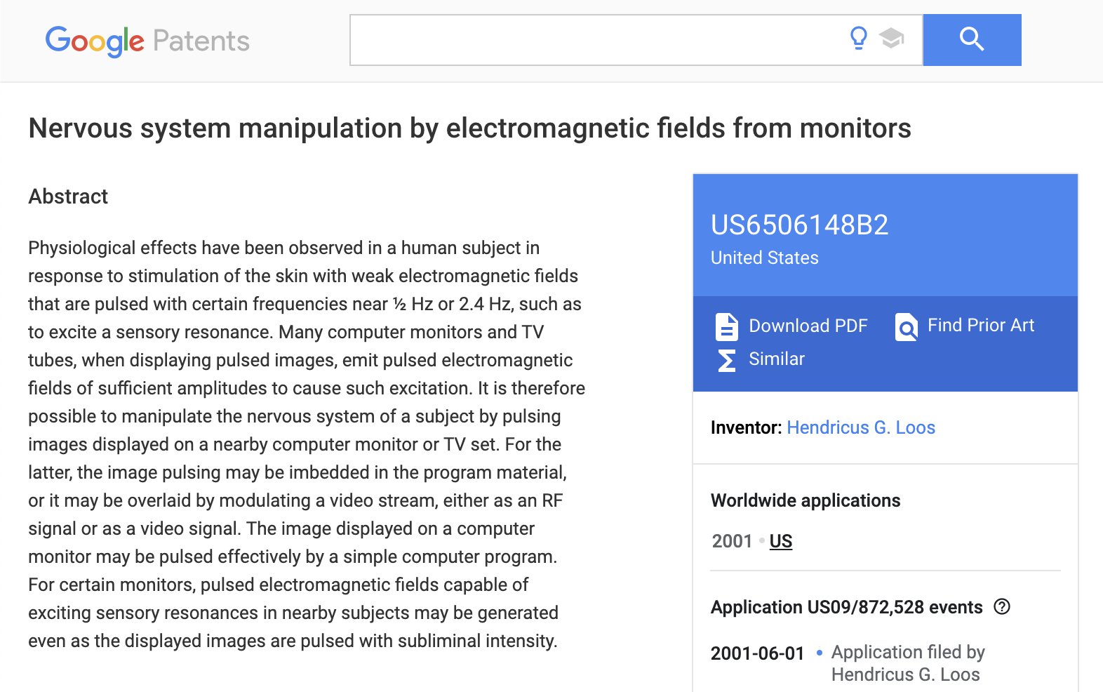
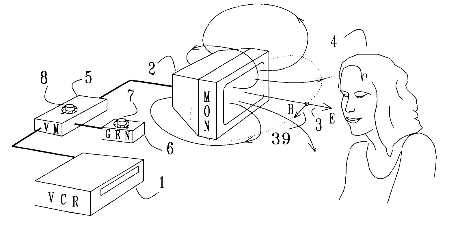
US PATENT
6,014,080 - BODY WORN ACTIVE AND PASSIVE TRACKING DEVICE --Tamper resistant
body-worn tracking device to be worn by offenders or potential
victims for use in a wireless communication system receiving
signals from a global positioning system (GPS).
US PATENT 6,017,302 -
SUBLIMINAL ACOUSTIC MANIPULATION OF NERVOUS SYSTEMS --In human
subjects, sensory resonances can be excited by subliminal
atmospheric acoustic pulses that are tuned to the resonance
frequency. The 1/2 Hz sensory resonance affects the autonomic
nervous system and may cause relaxation, drowsiness, or sexual
excitement, depending on the precise acoustic frequency near 1/2
Hz used. The effects of the 2.5 Hz resonance include slowing of
certain cortical processes, sleepiness, and disorientation. For
these effects to occur, the acoustic intensity must lie in a
certain deeply subliminal range. Suitable apparatus consists of
a portable battery-powered source of weak subaudio acoustic
radiation. The method and apparatus can be used by the general
public as an aid to relaxation, sleep, or sexual arousal, and
clinically for the control and perhaps treatment of insomnia,
tremors, epileptic seizures, and anxiety disorders. There is
further application as a nonlethal weapon that can be used in
law enforcement standoff situations, for causing drowsiness and
disorientation in targeted subjects. It is then preferable to
use venting acoustic monopoles in the form of a device that
inhales and exhales air with subaudio frequency.
US PATENT 6,051,594 -
METHODS AND FORMULATIONS FOR MODULATING THE HUMAN SEXUAL
RESPONSE
--The invention is directed to improved methods for modulating
the human sexual response by orally administering a formulation
of the vasodilator phentolamine to the blood circulation and
thereby modulating the sexual response on demand.
US PATENT 6,052,336 -
APPARATUS AND METHOD OF BROADCASTING AUDIBLE SOUND USING
ULTRASONIC SOUND AS A CARRIER --An ultrasonic sound source
broadcasts an ultrasonic signal which is amplitude and/or
frequency modulated with an information input signal originating
from an information input source. If the signals are amplitude
modulated, a square root function of the information input
signal is produced prior to modulation. The modulated signal,
which may be amplified, is then broadcast via a projector unit,
whereupon an individual or group of individuals located in the
broadcast region detect the audible sound.
Yikes! Take me Back to the
Main Page!